35
Input/output
settings
Intr
oduction
Connections
Basic operation
Switc
hing ima
g
es
Eff
ects
BPM sync
External de
vices
Video fader
Appendices
Switching Between Images
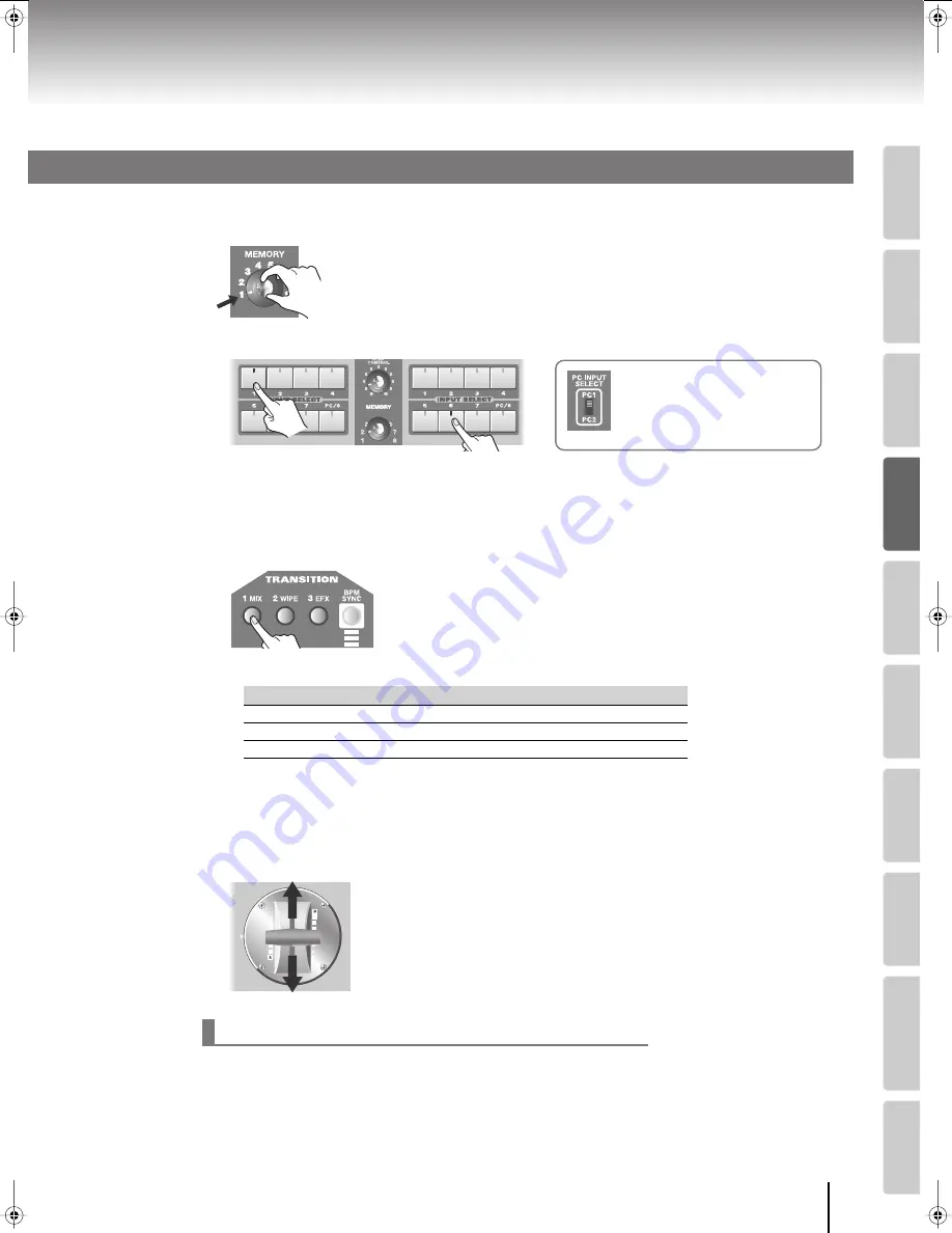
Here’s how to switch between the images being input to bus A and bus B of the video mixer.
1
Set the [MEMORY] knob to memory number 1.
* The factory preset settings are assigned to memory number 1. For details on
the [MEMORY] knob, refer to “Storing the Operating Panel Settings” (p. 28).
2
Use the INPUT SELECT buttons to select the images input to bus A and bus B.
* When you use the [PC INPUT SELECT] switch to switch the PC input, it will take some time for the input to stabilize.
We recommend that you use a monitor to verify the image.
* If you want to adjust the display position or other aspects of the PC input screen, refer to “Adjusting the PC Input
Image” (p. 54).
3
Use the TRANSITION buttons to select the desired transition effect.
Press one of the [1 MIX] [2 WIPE] [3 EFX] buttons to select the desired
transition. The selected button will light.
* With the factory presets, the TRANSITION buttons are assigned the following transition effects.
* You can change the transition effect that’s assigned to each TRANSITION button. For details, refer to “Changing
the Transition Assigned to Each TRANSITION Button” (p. 36).
* Depending on the type of transition and effect (p. 42), there are some combinations that cannot be used
simultaneously. For details, refer to “Effects that Cannot Be Used Simultaneously” (p. 107).
4
Operate the video fader to switch between the images of bus A and bus B.
To output the bus A image, move the video fader toward bus A.
To output the bus B image, move the video fader toward bus B.
If the video fader is not fully toward the bus A or bus B position, using the INPUT SELECT buttons to switch channels
will cause the image to be distorted, but this is not a malfunction.
Take the following action and make the following settings before using the INPUT SELECT buttons to switch images.
This will allow you to switch smoothly between images without any switching noise.
•
Set the video fader all the way toward the bus A or bus B position (the bus that is outputting the video).
•
Raise the value of the “Utility” menu item “Input Select Delay Time.”
Button
Menu item
Value
Effect
[1 MIX] button
1. Mix (Trans1)
001: Mix01
Dissolve
[2 WIPE] button
2. Wipe (Trans2)
008: Wipe03
Wipe
[3 EFX] button
3. Efx (Trans3)
192: SWipe88
Soft edge wipe
When using the INPUT SELECT buttons to switch images
Switching Between Two Images
Bus A
Bus B
If you’ve selected the [PC/8] button
Use the [PC INPUT SELECT] switch
to change between the PC1 and PC2
connector inputs.
Bus A
Bus B
V-8_e.book 35 ページ 2008年5月15日 木曜日 午後1時11分
Содержание V-8
Страница 114: ...For EU Countries For China ...
Страница 116: ...04903812 08 06 3N 0 4 9 0 3 8 1 2 0 3 ...


