background image


11


Panel descriptions


fig.05-02.eps


*

In the interest of product improvement, the specifications and/or appearance of this unit are subject to change without prior notice.


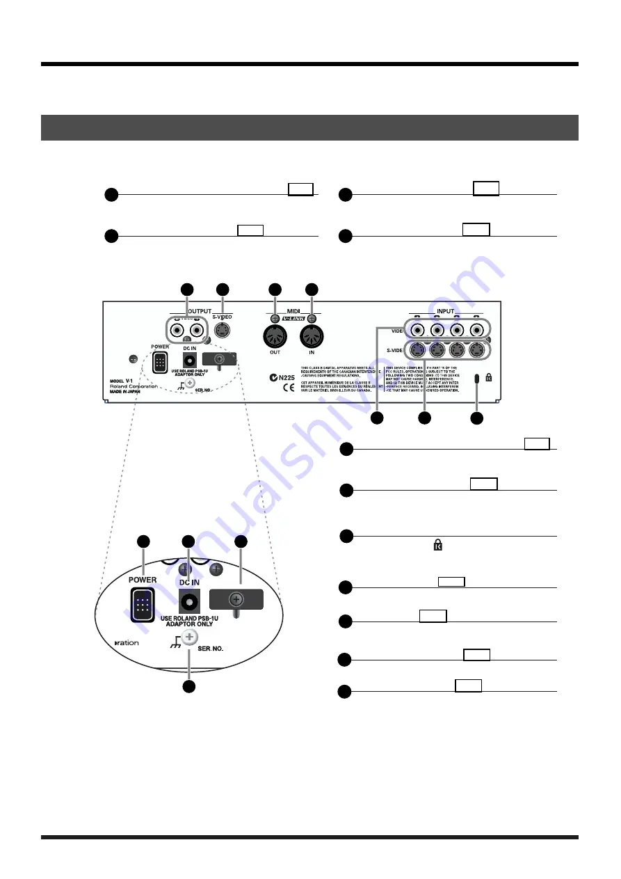
Rear panel

Secur ity Slot (    )
http://www.kensington.com/

5

Video (composite) input jacks (p.12)

These jacks accept the input of video
(composite) signals

6

S-video input jacks (p.12)

These jacks accept the input of video 
(S-video) signals

3

MIDI OUT connector (p.24)

MIDI messages are output from 
this connector

4

MIDI IN connector (p.23)

MIDI messages are received here

1

Video (composite) output jacks (p.12)

These jacks output the video 
(composite) signal

2

S-video output jack (p.12)

This jack outputs the video 
(S-video) signal

7

Theft-prevention lock receptacle

10

Power cable hook (p.12)

Use this to secure the power cable

11

Ground terminal (p.14)

Connect this to an exter nal ground

8

Power button (p.14)

Switches the power on/off

9

DC In jack (p.12)

Connect the AC adaptor here

5

6

4

1

2

11

9

10

7

8

3

3

5

6

4

1

2

11

9

10

7

8

3

3

Содержание V-1

Страница 1: ...ation of the unit Additionally in order to feel assured that you have gained a good grasp of every feature provided by your new unit Owner s manual should be read in its entirety The manual should be saved and kept on hand as a convenient reference Copyright 2004 ROLAND CORPORATION All rights reserved No part of this publication may be reproduced in any form without the written permission of ROLAN...

Страница 2: ...e following measures Reorient or relocate the receiving antenna Increase the separation between the equipment and receiver Connect the equipment into an outlet on a circuit different from that to which the receiver is connected Consult the dealer or an experienced radio TV technician for help This device complies with Part 15 of the FCC Rules Operation is subject to the following two conditions 1 ...

Страница 3: ...ff remove the AC adaptor from the outlet and request servicing by your retailer the nearest Roland Service Center or an authorized Roland distributor as listed on the Information page when The AC adaptor the power supply cord or the plug has been damaged or If smoke or unusual odor occurs Objects have fallen into or liquid has been spilled onto the unit or The unit has been exposed to rain or othe...

Страница 4: ...g a dry cloth to wipe all dust and other accumulations away from its prongs Also disconnect the power plug from the power outlet whenever the unit is to remain unused for an extended period of time Any accumulation of dust between the power plug and the power outlet can result in poor insulation and lead to fire Try to prevent cords and cables from becoming entangled Also all cords and cables shou...

Страница 5: ...ore using the unit you must allow it to stand for several hours until the condensation has completely evaporated Maintenance For everyday cleaning wipe the unit with a soft dry cloth or one that has been slightly dampened with water To remove stubborn dirt use a cloth impregnated with a mild non abrasive detergent Afterwards be sure to wipe the unit thoroughly with a soft dry cloth Never use benzi...

Страница 6: ...16 Using the input selector to switch video sources 17 Changing the transition effect 18 Mixing images 18 Wiping 18 Using compositing effects 19 Using P in P Picture In Picture to composite two screens 19 Superimposing text on the screen 20 Blacking out the output image 21 Changing the System settings 22 Using Lock mode 22 Switching between NTSC and PAL 22 Using MIDI to control the V 1 from an ext...

Страница 7: ...provide confirmation of the current operating status switching and mixing images is easy The Picture In Picture effect lets you show a miniaturized image inside a different image The Superimpose effect lets you remove a specified portion of an image and combine it with a different image This provides an easy way to superimpose text from the video output of your computer The V 1 s MIDI connectors l...

Страница 8: ...mbined with live video using the Superimpose feature fig 02 01 eps See p 16 for more about transitions See p 20 for more about Superimpose You can use the V 1 to add video to enhance your business presentations While displaying information created on your computer you can use the Picture In Picture feature to add photographed images of products or people fig 02 02 eps See p 19 for more about Pictu...

Страница 9: ...Before you begin The V 1 is shipped with the following items Make sure that you have all of them fig 04 01 eps Check the included items 1 2 3 4 1 2 3 4 The V 1 itself AC adaptor Power cable Owner s manual ...

Страница 10: ...he transition time 5 Transition Pattern knob p 18 p 19 Specifies the type of Wipe or P in P 2 Superimpose Level knob p 20 Adjusts the superimpose level 3 Superimpose button p 20 Switches the superimpose effect on off 7 A Input selectors p 17 Select input A 8 B Input selectors p 17 Select input B 11 Video fader indicator p 16 Indicates the position of the video fader 9 Mix button p 18 Switches the ...

Страница 11: ...ignals 3 MIDI OUT connector p 24 MIDI messages are output from this connector 4 MIDI IN connector p 23 MIDI messages are received here 1 Video composite output jacks p 12 These jacks output the video composite signal 2 S video output jack p 12 This jack outputs the video S video signal 7 Theft prevention lock receptacle 10 Power cable hook p 12 Use this to secure the power cable 11 Ground terminal...

Страница 12: ...ayer and take advantage of a wide range of creative possibilities fig 06 02 eps Making connections VTR Television Television Video camera DVD PLAYER PC AC adaptor Video projector Using the cable hook To AC Concent Video playback device Video output device Set the TV s input select to Video or External Input OUTPUT Audio L R Video S INPUT Audio L R Video S ...

Страница 13: ...the power on all devices before making any connections The video cables needed for making connections are not included with the V 1 You will need to obtain commercially available video cables If the cable length is not too long you will obtain a better image by using an S video cable to make connections However if you cannot avoid using an extremely long video cable use a video composite cable rat...

Страница 14: ...ettings 1 Press the rear panel POWER button Press the POWER button located on the rear panel All buttons and indicators on the front panel will go dark Turning the power off About the grounding connector Depending on the conditions in which you use it the V 1 s panel may feel slightly gritty to the touch This is due to an extremely low level of static electricity that poses absolutely no danger to...

Страница 15: ...that s connected to the V 1 s video output connector and verify that you see the image being output by the V 1 If everything is working properly the image s from the device s connected to the V 1 will be output If no video signal is being input a blue screen will be output 5 Switch the input channel If more than one video source is connected to the V 1 press the Input Select A buttons to verify th...

Страница 16: ...transition effect Mix or Wipe If the video fader is all the way up A or down B a single green video fader indicator will be lit If the video fader is between A and B a single red video fader indicator at the left of the video fader will be lit fig 07 01 2 eps When using a compositing effect P in P or Superimpose The green video fader indicator beside the background image will light If the video fa...

Страница 17: ...the input selector The input selector button will blink while the image transition takes place fig 07 03 eps The Transition Time knob will work only when the green video fader indicator is lit If you press an unlit Input Select button while turning the Transition Time knob the transition effect will end at that point You cannot press the Mix button or Wipe button while using the Transition Time kn...

Страница 18: ...tion pattern knob to select the type of wipe Knob settings on the left side select a wipe pattern Knob settings on the right side select P in P compositing fig 07 05 2 eps The wipe will occur in a single fixed direction for each type of wipe 3 Use the video fader or input selector to switch between images Changing the transition effect Mixing images Wiping Mix Horizontal wipe soft Wipe Pattern Hor...

Страница 19: ...n The setting of the Transition Time knob is ignored at this time If you want to layer image A on top of image B simply exchange A and B in the procedure described above Using compositing effects Using P in P Picture In Picture to composite two screens P in P Background Output Foreground The input selector buttons blink in one of two ways depending on the function you re using Blinking slowly When...

Страница 20: ...level knob to adjust the range that is cut out As desired you can adjust the range of color that will be cut out fig 07 07 4 eps If you want to superimpose image A on top of image B simply exchange A and B in the procedure described above Superimposing text on the screen Superimpose Background Output Superimposing Image The input selector buttons blink in one of two ways depending on the function ...

Страница 21: ... Press the Output button The Output button will blink a black screen will be output and the image will disappear fig 07 08 eps If you press the Output button once again the Output button will revert to steadily lit and the output image will reappear Blacking out the output image ...

Страница 22: ...hat switched will appear in the output image of video output 2 composite The next time you power up the V 1 it will start up in the mode To return to original mode Once again turn on the power while holding down the Output button and Mix button Using Lock mode Switching between NTSC and PAL Lock mode restricts the following operations You can t use the Input Select Mix Or Wipe P in P buttons unles...

Страница 23: ...unction that makes it easy to perform video in conjunction with music It s easy to use a V LINK compatible device to remotely control the V 1 V LINK lets you perform a wide variety of video effects that are linked with your musical performance Use a MIDI cable to connect your V LINK device to the V 1 For details on how to switch V LINK on off refer to the owner s manual of the V LINK device connec...

Страница 24: ...fer to the implementation chart Refer to your MIDI sequencer s manual for further information Controlling the V 1 from a connected P 1 Correspondence between controls and MIDI messages For the best image quality use an S video cable to connect the P 1 and V 1 MIDI messages shaded in the diagram are given in hexadecimal notation 5 3 4 1 6 7 2 5 3 4 1 6 7 2 5 Output button Message 3 bytes B0 02 xx x...

Страница 25: ...ence 2 1 4 Fader Control Parameter 2 2 V LINK Model ID 00H 51H For addresses marked by divide the data and transmit it as two bytes an upper nibble upper 4 bits and lower nibble lower 4 bits Example If the original data is BCH send 0BH as the first byte and send 0CH as the second byte For reception the data will be ignored unless the two bytes are received together If the value is shown as this is...

Страница 26: ...H 1 16 Ch 10H 00H 02H V LINK MIDI Rx Channel Color 10H 00H 03H V LINK Note Message Enabled 00H 03H Note Mode OFF 49Keys Mode Assign Mode Note Assign 10H 00H 04H V LINK Fast Control Enabled 10H 00H 05H V LINK MMC Control Mode 10H 00H 06H V LINK MTC Control Mode 10H 00H 07H V LINK Auto Mix Mode Address Parameter Name Sys Ex Value Meaning of Value 10H 10H 00H V LINK Rx Setting Playback Speed 10H 10H ...

Страница 27: ...rns Change 1 5 Control various parameters 7 31 Control various parameters 64 95 Control various parameters Program Select inputs INPUT 1 4 Change 0 3 0 7 0 3 0 7 Transition patterns 1 8 Sytem Exclucive Set parameters V LINK Song position Song select Tune System Clock Realtime System Common Command Aux Messages All sound off Reset all controllers Local ON OFF All Notes off Active Sense System Reset...

Страница 28: ...r 0 the transition effect will not occur when you use the input selector to switch images The images don t switch as specified by the Transition Time knob setting If two images are displayed under the conditions listed below operating the input selector will not switch the images according to the specified transition time If the video fader is stopped midway If you re using P in P If you re using ...

Страница 29: ... signal 0 286 mVp p 75 ohms Interface MIDI 5 pin DIN type Connectors Input Video composite 1 4 RCA phono type S video 1 4 4 pin mini DIN type Output Video composite 2 RCA phono type S video 1 4 pin mini DIN type MIDI IN 5 pin DIN type MIDI OUT 5 pin DIN type Transition Effects Mix Wipe 4 types P in P 4 types Compositing Effects Superimpose remove black Power Supply DC 9 V AC Adaptor Current Draw 1...

Страница 30: ...30 ...

Страница 31: ...usica e Audio Roland Portugal S A Cais Das Pedras 8 9 1 Dto 4050 465 PORTO PORTUGAL TEL 022 608 00 60 POLAND MX MUSIC SP Z O O UL Gibraltarska 4 PL 03664 Warszawa POLAND TEL 022 679 44 19 GREECE STOLLAS S A Music Sound Light 155 New National Road Patras 26442 GREECE TEL 2610 435400 RUSSIA MuTek 3 Bogatyrskaya Str 1 k l 107 564 Moscow RUSSIA TEL 095 169 5043 SPAIN Roland Electronics de España S A C...

Страница 32: ...03560189 04 3 2KS ...

Отзывы: