background image

19 

Step 2

  Press the “Security” button on any device in the network for less than 3 seconds. 

This should be done within 1 minute. 


Step 3

  Wait for the connection to complete. 


The “Power” LED on both devices will blink evenly at 1-second intervals until the 

operation succeeds or fails. If the connection succeeds, it will illuminate steadily. If an error 
occurs, the power LED on the adder will blink unevenly until the “Security” button on the 
adder is pressed again or the joiner is reset. 
 

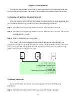
A

PLC

B

PLC

C

PLC

A and B form an AVLN

C wants to join the AVLN

Press NMK button on B less than 3 sec.

Press NMK button on C less than 3 sec.

B becomes 

“adder”

C becomes 

“joiner”

C accepts NMK from B

A

PLC

A

PLC

B

PLC

B

PLC

C

PLC

A and B form an AVLN

C wants to join the AVLN

Press NMK button on B less than 3 sec.

Press NMK button on C less than 3 sec.

B becomes 

“adder”

C becomes 

“joiner”

C accepts NMK from B


5.3 Leaving a Network 


If you want to remove a device from an existing network, follow the following 

procedures: 
 

Step 1

  Press the “Security” button on the device to be removed for at least 10 seconds. 


Step 2

  Wait for the device to reset. 


The “Power” LED on the device to be removed will momentarily extinguish. It will start 

to blink after it has restarted. Then it will illuminate steadily if no error occurs. You can then 
disconnect the device. 
 

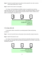
A

PLC

B

PLC

C

PLC

A, B and C form an AVLN

A wants to leave the AVLN

Press NMK button on A more than 10 sec.

A computes random NMK

A resets and restarts

A

PLC

A

PLC

B

PLC

B

PLC

C

PLC

A, B and C form an AVLN

A wants to leave the AVLN

Press NMK button on A more than 10 sec.

A computes random NMK

A resets and restarts
 

Содержание HP-5001

Страница 1: ......

Страница 2: ...rove defective following their purchase the buyer and not this company its distributor or its dealer assumes the entire cost of all necessary servicing repair and any incidental or consequential damag...

Страница 3: ...ter 5 2 1 Ethernet Port 5 2 2 Buttons 5 2 3 LEDs 6 Chapter 3 Utility Software Installation 7 Chapter 4 Using the Utility Software 14 4 1 Main Tab 14 4 2 Privacy Tab 15 4 3 Diagnostics Tab 16 4 4 About...

Страница 4: ...s Consumes less than 1W of power in power saving mode 1 2 Application High definition HD and standard definition SD video distribution Broadband Internet sharing Internet Protocol Television IPTV and...

Страница 5: ...perating System Utility can support Windows 2000 XP Vista 7 CPU Intel Pentium III 2 0GHz or higher RAM 128MB at least Free Disk Space 20MB at least Network Interface Fast Ethernet 100Mbps network inte...

Страница 6: ...set Press and hold the reset button for 3 seconds to restore the powerline adapter to factory defaults Security Group Press and hold the Security Group button for more than 10 seconds to randomize the...

Страница 7: ...ork activity Off No Ethernet connection Power Green On Powered on Flashing In power saving mode Device resetting Synchronizing password Off Powered off PLC Green Orange Red On Green PHY RATE 80Mbps Or...

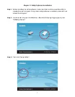
Страница 8: ...re make sure that no other powerline utility is installed on your computer If any other utility software is installed uninstall it and reboot the computer Step 2 Insert the CD into your CD ROM drive W...

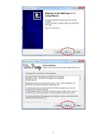
Страница 9: ...8 Note You will get the following image if your computer did not install WinPcap4 1 2 before Please click Apply to install WinPcap4 1 2...

Страница 10: ...9...

Страница 11: ...10...

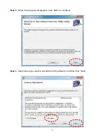
Страница 12: ...11 Step 4 When the setup wizard appears click Next to continue Step 5 Select where you want to install the utility software and then click Next...

Страница 13: ...12...

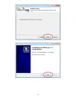
Страница 14: ...plete click Close Step 7 An icon will appear on your desktop Click the icon to open the utility software Note You can manage all the connected powerline adapters with the utility software However inst...

Страница 15: ...ftware will scan for other local powerline adapters Rename Select a device and click Rename to rename the device Enter Password By default this column is blank Select a device and click Enter Password...

Страница 16: ...gs If the network name is modified to anything other than the default the network type in the Main tab will be changed to Private Set Local Device Only This button is used to change the network name a...

Страница 17: ...ics tab displays the system information and history of all remote devices The upper panel displays technical data concerning the software and hardware on the host computer and the lower panel displays...

Страница 18: ...17 4 4 About Tab The About tab contains some basic information about the software You can also enable or disable the autoscan function under Preferences...

Страница 19: ...the connection succeeds it will illuminate steadily If an error occurs the power LED on the adder will blink unevenly until the Security button on the adder is pressed again or the joiner is reset A P...

Страница 20: ...m an AVLN C wants to join the AVLN Press NMK button on B less than 3 sec Press NMK button on C less than 3 sec B becomes adder C becomes joiner C accepts NMK from B 5 3 Leaving a Network If you want t...

Страница 21: ...posure limits human proximity to the antenna shall not be less than 2 5cm 1 inch during normal operation Federal Communications Commission FCC RF Exposure Requirements SAR compliance has been establis...

Страница 22: ...21...

Отзывы: