4-27
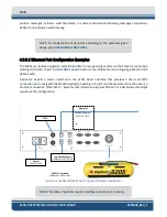
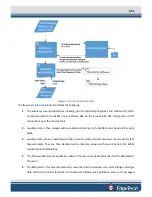
, the 6205s sonar interface connects to the sonar head via deck cable. Time and 1PPS,
navigation, heading, roll, pitch, and heave data from supporting sensors via COM ports 1, 2, and/or 3 and
1PPS, are inputted at sonar interface, passed through the deck cable, and processed by sonar processor
in sonar head.
These processed navigation and attitude data are transmitted (along with the raw side-scan data) with a
common timestamp up the deck cable to the 6205s sonar interface. They are then passed to the topside
computer through an Ethernet cable and via the 100Mbps link on an Ethernet port (IP Address:
192.9.0.99).
The topside computer then processes the data using the Discover Bathymetric software to send
amplitude, angle, and range data to the 3rd party software for logging and post-processing. This process
is explained in further detail in the following section. The 3rd party software and Discover Bathymetric
processors may all run on the same topside computer.
4.2.3.1
Serial Port Configuration Examples
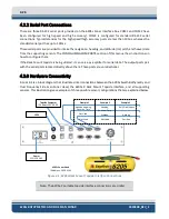
depicts a sensor interfacing to the 6205s sonar interface that provides time and
1PPS, navigation (latitude/longitude), heading, roll, pitch, and heave data over one serial connection—
such as a NovaTel ProPak 6 or Applanix POS-MV (RS232 data output, not Ethernet data output). As
depicted in
the sensor is connected to COM1.
Example 2 shows the most common interfacing scenario, a GNSS that provides navigation and heading
and time data, accompanied by a separate motion sensor for heave/roll/pitch measurements.
The COM ports should be assigned as such:
•
COM1 = MRU (Roll, Pitch, Heave)
•
COM2 = GNSS (Navigation and Heading and Time)
•
1PPS = 1PPS TTL from the GNSS unit
These assignments may be interchanged between COM1 and COM2 because both ports have been
configured for high speed and accuracy. COM3 should not be used in this scenario.
Example 3 portrays a situation where the GNSS does not provide heading data. In this case, three sensors
are required: a GNSS for navigation (latitude/longitude/height and time), a Gyrocompass for heading, and
a motion sensor for roll, pitch, and heave measurements.
Therefore, all three COM ports should be used and assigned as follows:
•
COM1 = MRU (Roll, Pitch, Heave)
•
COM2 = Gyrocompass (Heading)
•
COM3 = GNSS (latitude/longitude/time)
•
1PPS = 1PPS TTL from the GNSS unit
The sensors allocated to COM1 and COM2 may be interchanged for the same reason stated in the second
example. GNSS data, or latitude and longitude and height data, must be allotted to COM3 because
Содержание 6205S
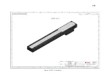
Страница 27: ...2 10 Figure 2 5 Acoustic Center Location in X Y and Z and Bolt Pattern of Standard 6205s 0019604...
Страница 28: ...2 11 Figure 2 6 Acoustic Center Location in X Y and Z Dimensions and Bolt Pattern with Adaptor Flange 0021206...
Страница 37: ...3 20 Figure 3 5 6205s Exploded View with Adaptor Flange...
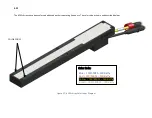
Страница 38: ...3 21 Figure 3 6 6205s Transducer...
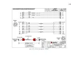
Страница 40: ...3 23 Figure 3 8 6205s Wiring Diagram 0019627...
Страница 86: ...8 69 Figure 8 22 Checking all COM Ports...
Страница 92: ...8 75 Figure 8 28 UDP broadcast settings example Figure 8 29 Eth1 data output...
Страница 94: ...8 77 Figure 8 31 1PPS settings example Falling Edge and 1msec duration...

