4-20
2000-DSS Combined Sonar
0009335_REV_D
4.1.2
2000 Digital Telemetry Link
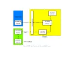
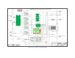
A block diagram of the 2000 Digital Telemetry Link electronics is shown in
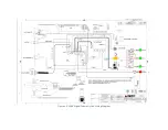
. The wiring diagram
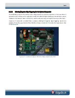
, and the electronics chassis is shown in
F
IGURE
4-3
. The main hardware elements in
the 2000 Digital Telemetry Link include the following components and circuit boards:
POWER:
The Power board 24 VDC on J1 from the 24 VDC Power
Supply and generates the 400 VDC tow vehicle power which is
output to the tow vehicle on J13 combined with the frequency
shift keyed (FSK) responder trigger signal input on J10 and the
ADSL downlink command and uplink data signals. The command
signals are input and the data signals are output on J14. The
Power board also in5, +12 and +15 VDC power supplies,
where +12 VDC is output on J4 to the fan and on J6 to the ADSL
Modem board.
24 VDC POWER SUPPLY:
The 24 VDC Power Supply inputs AC power from the Power Entry
module to ge24 VDC which is output to the Power board.
POWER ENTRY:
The Power Entry module filters the AC power and connects it to
the 24 VDC Power Supply through the front panel power switch.
ADSL MODEM:
The ADSL Modem board converts the uplink data ADSL signals
received from the tow vehicle and input on the ADSL connector
from the Power board into Ethernet 10/100/1000BaseT signals
which are output to the 2000 Topside Processor. Similarly, the
ADSL Modem board converts the downlink Ethernet
10/100/1000BaseT based command signals from the 2000
Topside Processor into the ADSL downlink command signals
which are output on the ADSL connector to the Power board for
transmission to the tow vehicle. The ADSL Modem board also
serves as an Ethernet switch to provide Ethernet connections on
J1 to the 2000 Topside Processor, on J3 to the Wireless Router
and on J4 to the Net Burner board on the Power board, placing
all of these devices on the same LAN. +12 VDC power is input on
the DC connector from the Power board.
NET BURNER:
The Net Burner board mounts to and connects directly to the
Power board to provide Power board diagnostics, tow vehicle
power control, positive and negative trigger edge selection, and
sensor monitoring. An Ethernet connection to the Net Burner
board is provided on J3 from the ADSL Modem board. Power is
input from the Power board.
Содержание 2000-DSS
Страница 20: ......
Страница 56: ...Figure 4 2 2000 Digital Telemetry Link Electronics Block Diagram...
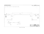
Страница 57: ...Figure 4 3 2000 Digital Telemetry Link Wiring Diagram...
Страница 59: ...Figure 4 4 Tow Vehicle Electronic Block Diagram...
Страница 60: ...Figure 4 5 Tow Vehicle Interconnect Drawing...
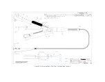
Страница 63: ...Figure 4 6 Armored Cable PMI Grip Unterminated Topside...
Страница 64: ...Figure 4 7 Test Cable...
Страница 77: ...5 13 Figure 5 16 Magnetic Declination Estimated Value Screen...
Страница 79: ...5 15 getDeclination CR Figure 5 18...
Страница 80: ......
Страница 94: ......
Страница 96: ......
Страница 98: ......

