ECS P41G Series Скачать руководство пользователя страница 11

8

Motherboard User’s Guide

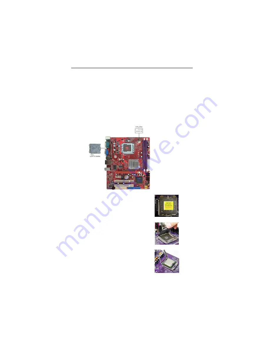
Installing the Processor

This motherboard has a 

LGA775

 socket for the latest 

Intel

®

 Core

TM

 2 Quad/

Intel

®

 Core

TM 

2 Duo/Pentium

®

 Dual-Core (E21xx series)/Celeron

®

 Dual-

Core

/Celeron

®

 4xx series

 processors. When choosing a processor, consider

the performance requirements of the system. Performance is based on the
processor design, the clock speed and system bus frequency of the processor,
and the quantity of internal cache memory and external cache memory.

CPU Installation Procedure

Follow these instructions to install the CPU:

B.   Unload the cap

Use thumb & forefinger to hold the
lifting tab of the cap.

Lift the cap up and remove the cap
completely from the socket.

C.   Open the load plate

Use thumb & forefinger to hold the
hook of the lever, pushing down and
pulling aside unlock it.

Lift up the lever.

Use thumb to open the load plate.
Be careful not to touch the contacts.

D.   Install the CPU on the socket

Orientate CPU package to the socket.
Make sure you match triangle marker
to pin 1 location.

A.   Read and follow the instructions
      shown on the sticker on the CPU cap.

Содержание P41G Series

Страница 1: ...el Corporation Microsoft MS DOS and Windows 2000 XP Vista are registered trademarks of Microsoft Corporation AMI is a trademark of American Megatrends Inc It has been acknowledged that other brands or...

Страница 2: ...vices 13 Install Other Devices 15 Expansion Slots 18 Chapter 3 BIOS Setup Utility 20 Introduction 20 Running the Setup Utility 20 Standard CMOS Setup Page 21 Advanced Setup Page 22 Advanced Chipset Se...

Страница 3: ...icrosoft Therefore it might happen under Windows XP that a dialogue box shown as below pop out warning you this software has not passed Windows Logo testing to verify its compatibility with Windows XP...

Страница 4: ...the built in USB 2 0 providing higher bandwidth implementing Universal Serial Bus Specification Revision 2 0 and is compliant with UHCI 1 1 and EHCI 1 0 It supports High Definition Audio Codec and pro...

Страница 5: ...memory is 4 GB System Memory Controller Support DDR2 SDRAM with up to maximum memory of 4 GB PCI Express Graphics Interface Support One PCI Express x16 slot PCI Bus Interface Support PCI Revision 2 3...

Страница 6: ...rameters and memory timing CPU and memory timing The firmware can also be used to set parameters for different processor clock speeds Note Hardware specifications and software items are subject to cha...

Страница 7: ...on cable The Software support CD Optional Accessories You can purchase the following optional accessories for this motherboard The Extended USB module The CNR v 90 56K Fax Modem card The SerialATAcabl...

Страница 8: ...Install this motherboard in a system chassis case Connect any extension brackets or cables to headers connectors on the motherboard Install peripheral devices and make the appropriate connections to h...

Страница 9: ...Front Panel USB Pow er Select Jumper 8 F_USB1 2 Front Panel USB headers 9 SPK1 Speaker header 10 IDE Primary IDEconnector 11 CLR_CMOS Clear CMOS jumper 12 FDD Floppy disk drive connector 13 SPDIFO1 SP...

Страница 10: ...e COM port to connect serial devices such as mice or fax modems COM1 is identified by the system as COM VGA Port Use the VGA port to connect VGA devices LAN Port Connect an RJ 45 jack to the LAN port...

Страница 11: ...e memory and external cache memory CPU Installation Procedure Follow these instructions to install the CPU B Unload the cap Use thumb forefinger to hold the lifting tab of the cap Lift the cap up and...

Страница 12: ...offers greater bandwith and density in a smaller packahe along with a reduction in power consumption In addition DDR2 SDRAM offers new features and functions that enable a higher clock rate and data r...

Страница 13: ...re is a notch on the DIMM socket that you can install the DIMM module in the correct direction Match the cutout on the DIMM module with the notch on the DIMM socket 3 Install the DIMM module into the...

Страница 14: ...tting Normal Short Pins 1 2 Clear CMOS Short Pins 2 3 Note To avoid the system unstability after clearing CMOS we recommend users to enter the main BIOS setting page to Load Optimal De faults and then...

Страница 15: ...e sure your case has an I O cover plate matching the ports on this motherboard Install the motherboard in a case Follow the case manufacturer s instructions to use the hardware and internal mounting p...

Страница 16: ...r on the motherboard Pin Signal Pin Signal 1 SPDIFOUT 2 5VA 3 KEY 4 GDN SPDIFO1 S PIF Out Header S PDIF Sony Plilips Digital Interface is a standard audio transfer file format and allows the transfer...

Страница 17: ...bracket cable onto the F_USB1 F_USB2 header 3 Remove a slot cover from one of the expansion slots on the system chassis Install an extension bracket in the opening Secure the extension bracket to the...

Страница 18: ...w LPT Onboard parallel port Header This header allows the user to connect to the printer scanner or devices Pin Signal Pin Signal 1 STROBE 2 PD0 3 PD1 4 PD2 5 PD3 6 PD4 7 PD5 8 PD6 9 PD7 10 ACK 11 BUS...

Страница 19: ...Master device connects to the end of the cable Install the device s and connect power from the system power supply Use the cable provided to connect the device s to the Primary IDE channel connector...

Страница 20: ...in Signal 1 CD IN L 2 GND 3 GND 4 CD IN R Analog Audio Input Connector If you have installed a CD ROM drive or DVD ROM drive you can connect the drive audio cable to the onboard sound system When you...

Страница 21: ...18 Motherboard User s Guide Expansion Slots This motherboard has one PCI Ex16 one PCI Ex1 and two 32 bit PCI slots...

Страница 22: ...Base Specification revsion 1 0a Follow the steps below to install an PCI Express PCI expansion card 1 Locate the PCI Express or PCI slots on the motherboard 2 Remove the blanking plate of the slot fr...

Страница 23: ...e hardware installed in or connected to the motherboard such as the CPU system memory disk drives etc Running the Setup Utility Every time you start your computer a message appears on the screen befor...

Страница 24: ...the setting CDROM If you have an ATAPI device with removable media e g a ZIP drive or an LS 120 select Floptical If you have already changed the setup utility press F10 to save those changes and exit...

Страница 25: ...tup NumLock Status APIC Mode 1st Boot Device 2nd Boot Device 3rd Boot Device Hard Disk Drives Removable Drives CD DVD Drives Boot Other Device TM1 Enabled Disabled Enabled Enabled On Enabled ST3100034...

Страница 26: ...o view the following screen f Specifies the boot sequence from the available devices CMOS Setup Utility Copyright C 1985 2005 American Megatrends Inc Hard Disk Drives Move Enter Select Value F10 Save...

Страница 27: ...anced Chipset Setup Help Item DRAM Frequency Configure DRAM Timing bySPD VGA Share Memory DVMT Mode Select DVMT FIXED Memory HPET Move Enter Select Value F10 Save Esc Exit F1 General Help F9 Load Defa...

Страница 28: ...rements HPET This item enables or disables HPET High Performance Event Timer support This page sets up some parameters for peripheral devices connected to the system CMOS Setup Utility Copyright C 198...

Страница 29: ...allel Port Parallel Port IRQ Use this item to assign IRQ to the parallel port OnBoard SATA Controller Use this item to enable or disable the onboard SATAcontroller OnBoard LAN Function Use this item t...

Страница 30: ...d Resume By PS2 KB S3 Disabled Resume By PS2 MS S3 Disabled Resume on RTC Alarm Disabled Soft off By PWR BTTN If the item is set to Instant Off then the power button causes a software power down If th...

Страница 31: ...me By PS 2 KB S3 This item enables or disables you to allow keyboard activity to awaken the system from power saving mode Press Esc to return to the main menu setting page Resume By PS 2 MS S3 This it...

Страница 32: ...n Disabled Enabled CMOS Setup Utility Copyright C 1985 2005 American Megatrends Inc Smart Fan Function Move Enter Select Value F10 Save Esc Exit F1 General Help F9 Load Default Settings Help Item Opti...

Страница 33: ...tio Actual Value 17 CPU Frequency 200MHz CPU Over clocking Func Disabled Auto Detect DIMM PCI Clk Enabled Spread Spectrum Enabled Manufacturer This item displays the information of current manufacture...

Страница 34: ...values for accessing the best performance Supervisor Password Page This page helps you set up some parameters for the hardware monitoring function of this motherboard CMOS Setup Utility Copyright C 19...

Страница 35: ...es that you have made in the Setup Utility and exit the Setup Utility When the Exit Without Saving dialog box appears press Y to discard changes and exit or press N to return to the main menu CMOS Set...

Страница 36: ...ion depending on your operating system If your operating system is Windows 2000 XP Vista it will automatically install all the drivers and utilities for your motherboard Installing Support Software 1...

Страница 37: ...dMe brings you to the Install Path where you can find out path names of software driver Auto Installing under Windows 2000 XP Vista If you are under Windows 2000 XP please click the Setup button to ru...

Страница 38: ...Setup Procedure users should use one of the following two methods to install the driver after the system restart Method 1 Run Reboot Setup Windows Vista will block startup programs by default when in...

Страница 39: ...36 Motherboard User s Guide Follow these instructions to Disable Vista UAC function 1 Go to Control Panel 2 Select Classic View 3 Set User Account...

Страница 40: ...nserting the support CD ROM 2 A software menu appears Click the software you want to install 3 Follow onscreen instructions to install the software program step by step until finished 4 Select Turn Us...

Отзывы: