


H61H2-M8 USER MANUAL
46
Chapter 3
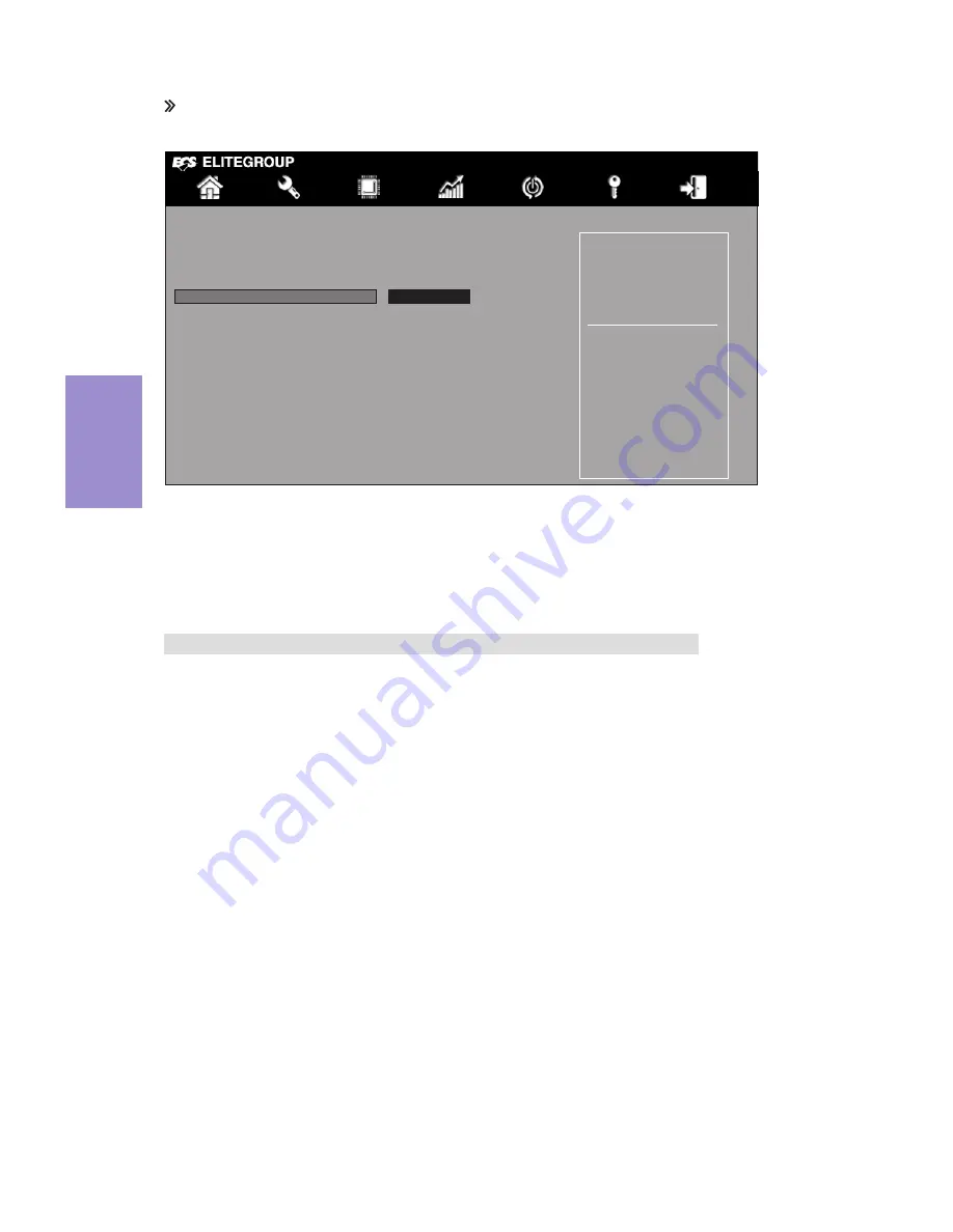
ME Configuration
Scroll to this item and press <Enter> to view the following screen:
ME FW Version (8.1.30.1350)
This item shows the ME FW version.
Press <Esc> to return to the Chipset Menu page.
ME Subsystem Help
Main
Advanced
Chipset
M.I.B III Boot Security Exit
+/- : Change Opt.
Enter/Dbl Click : Select
: Select Screen
/Click: Select Item
F1: General Help
F2: Previous Values
F3: Optimized Defaults
F4: Save & Exit
ESC/Right Click: Exit
Enable/Disable ME Firm-
ware
ME Control (Enabled)
Use this item to enable or disable ME Firmware.
Management Engine Technology Configuration
ME FW Version
8.1.30.1350
ME Control
Enabled
Содержание H61H2-M8
Страница 8: ...Chapter 1 4 H61H2 M8 USER MANUAL Motherboard Components ...
Страница 10: ...Chapter 1 6 H61H2 M8 USER MANUAL I O Ports Or ...
Страница 12: ...Chapter 1 8 H61H2 M8 USER MANUAL Memo ...
Страница 30: ...Chapter 2 26 H61H2 M8 USER MANUAL Connect the case speaker cable to SPK 5 SPK Speaker header ...
Страница 32: ...Chapter 2 28 H61H2 M8 USER MANUAL Memo ...
Страница 66: ...62 H61H2 M8 USER MANUAL Chapter 5 Memo ...