58
B75H2-M2 USER MANUAL
Chapter 4
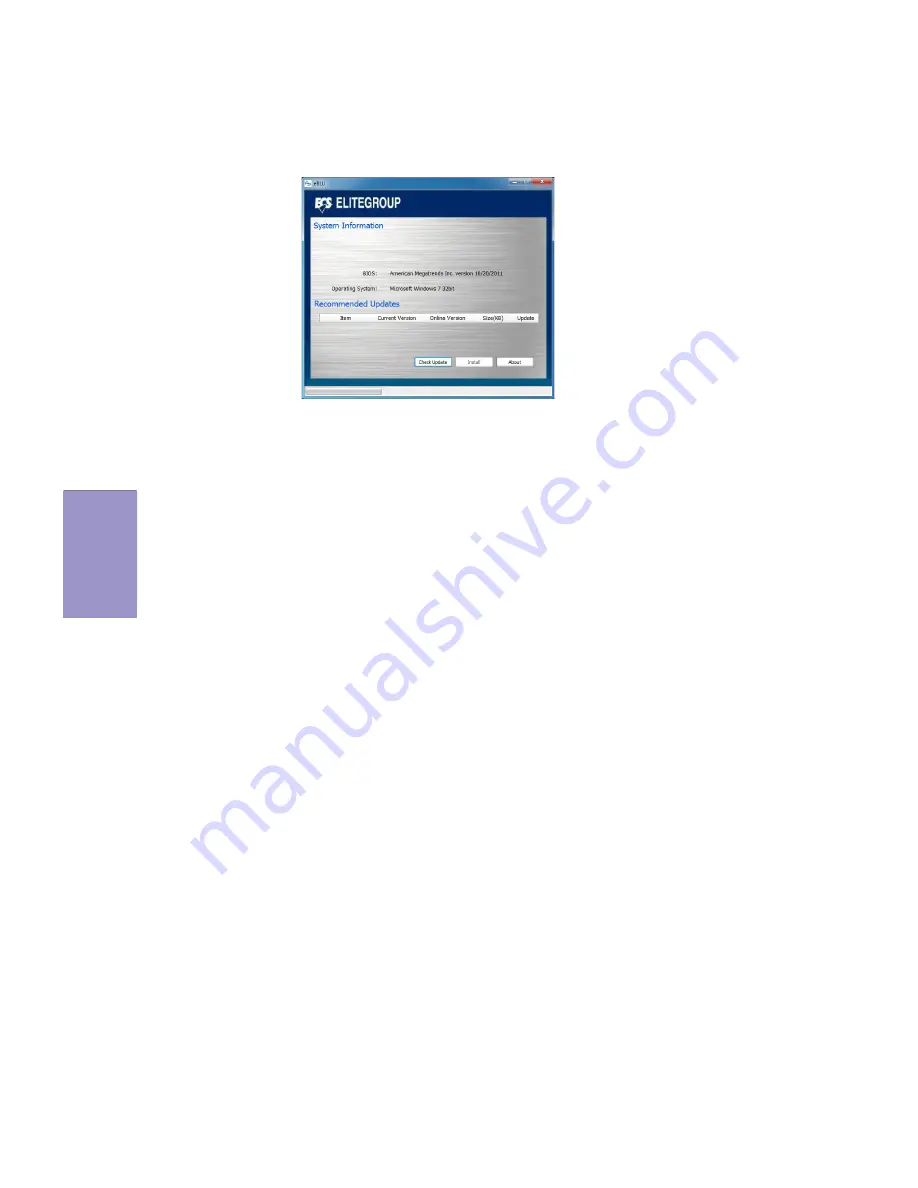
eBLU
ECS eBLU utility makes BIOS update faster and easier. eBLU will list the latest BIOSwith a default check-mark. Click”install” button to install.
Страница 1: ...been tested and found to comply with the limits for a Class B digital device pursuant to Part 15 of the FCC Rules These limits are designed to provide reasonable protection against harmful interferen...
Страница 2: ...age 7 Hpage 27 Hpage 55 Installing the Motherboard IntroducingtheMotherboard Provides information on us ing the BIOS Setup Utility Describes the motherboard software Limits and methods of mesurement o...
Страница 3: ...ve 21 ConnectingCaseComponents 22 Front Panel Header 24 TABLE OF CONTENTS Preface i Chapter 1 1 Introducing the Motherboard 1 Introduction 1 PakageContents 1 Specifications 2 MotherboardComponents 4 I...
Страница 4: ...ling under Windows XP Vista 7 55 Running Setup 55 ManualInstallation 57 ECSUtilitySoftware IntelligentEZUtility 57 Chapter 5 59 Trouble Shooting 59 Start up problems during assembly 59 Start up proble...
Страница 5: ...s and two USB 2 0 headers support additional four USB 2 0 ports and four USB 3 0 ports two USB 3 0 ports at the rear panel and one USB 3 0 header sup ports additional two USB 3 0 ports The gray USB 2...
Страница 6: ...ote wake up support Realtek ALC662 6 Ch High Definiton Audio Codec Compliant with HD audio specification Audio LGA1155 socket for new 3rd Generation Intel CoreTM family Pentium Celeron processors Supp...
Страница 7: ...STR S3 STD S4 Supports Hardware Monitor Audio LAN can be disabled in BIOS F7 hot key for boot up devices option Supports Over Clocking Supports Pgup clear CMOS Hotkey Has PS2 KB Model only Supports Du...
Страница 8: ...Chapter 1 4 B75H2 M2 B75H2 M2 B75H2 M2 B75H2 M2 B75H2 M2 USER MANUAL Motherboard Components...
Страница 9: ...TA2 5 Serial ATA 3 0 Gb s connectors 8 SATA1 Serial ATA 6 0 Gb s connector 9 F_PANEL Front panel switch LED header 10 CASE CASE open header 11 ME_UNLOCK ME unlock header for factory use only 12 F_USB1...
Страница 10: ...vice to the DVI port or HDMI port 5 USB 3 0 Ports Use the USB 3 0 ports to connect USB 3 0 devices 6 LAN Port Connect an RJ 45 jack to the LAN port to connect your computer to the Network 7 Line in bl...
Страница 11: ...n the motherboard Place the motherboard over the mounting brackets and secure the motherboard onto the mounting brackets with screws Follow these safety precautions when installing the motherboard Wea...
Страница 12: ...ion shows the location of the motherboard jumpers Pin 1 is labeled To avoid the system instability after clearing CMOS we recommend users to enter the main BIOS setting page to Load Default Settings a...
Страница 13: ...nge the settings in the system Setup Utility We strongly recommend you do not over clock processor or other compo nents to run faster than their rated speed The following illustration shows CPU instal...
Страница 14: ...IHS Intergraded Heat Spreader Engage the load lever while pressing down lightly onto the load plate Secure the load lever with the hook under retention tab Then the cover will flick automatically Plea...
Страница 15: ...board and processor socket Avoid using cooling fans with sharp edges in case the fan casing and the clips cause serious damage to the motherboard or its components To achieve better airflow rates and...
Страница 16: ...onents or metal parts Always wear a grounding strap when you handle the modules You must install at least one module in any of the two slots Total memory capacity is 32 GB Refer to the following to in...
Страница 17: ...es by adding hardware that performs tasks that are not part of the basic system PCIEX16 Slot The PCI Express x16 slot is used to install an external PCI Ex press graphics card that is fully compliant...
Страница 18: ...ectly seated in the slot 3 Secure the metal bracket of the card to the system case with a screw 1 For some add on cards for example graphics adapters and network adapt ers you have to install drivers...
Страница 19: ...ANUAL 2 4 5 Connecting Optional Devices Refer to the following for information on connecting the motherboard s optional devices No Components No Components 1 SATA1 5 5 USB3F 2 CASE 6 TPM 3 ME_UNLOCK 7...
Страница 20: ...asier PC assembly It eliminates limitations of the current Parallel ATA interface But main tains register compatibility and software compatibility with Parallel ATA 1 SATA1 5 Serial ATA connectors 2 C...
Страница 21: ...g within less time The motherboard has two USB 2 0 headers supporting four USB 2 0 ports Addition ally some computer cases have USB ports at the front of the case If you have this kind of case use aux...
Страница 22: ...ling a micro con troller that can store secured information and implementations of that specifica tion 6 TPM Trusted Platform Module header This Motherboard implements one USB 3 0 header supporting 2...
Страница 23: ...s This header supports HD audio by default If you want connect an AC 97 front panel audio to HD onboard headers please set as below picture 8 F_AUDIO Front Panel Audio Header This is an optional heade...
Страница 24: ...nel please don t tick off Disabled Front Panel Detect For reference only AC 97 Audio Configuration To enable the front panel audio connector to sup port AC97 Audio mode If you use AC 97 Front Panel pl...
Страница 25: ...low to install the SATA hard drives To install the Serial ATA SATA hard drives use the SATA cable that supports the Serial ATA protocol This SATA cable comes with a SATA power cable You can connect ei...
Страница 26: ...alled the motherboard into a case you can begin connecting the motherboard components Refer to the following Connect the CPU cooling fan cable to CPU_FAN Connect the system cooling fan connector to SY...
Страница 27: ...4 pin power cable the latches of power cable and the ATX match perfectly Connecting 24 pin power cable 24 pin power cable Connect the standard power supply connector to ATX_POWER Connect the auxiliary...
Страница 28: ...orting the reset function requires connecting pin 5 and 7 to a momentary con tact switch that is normally open When the switch is closed the board resets and runs POST Power Switch Supporting the powe...
Страница 29: ...Chapter 2 25 B75H2 M2 USER MANUAL Connect the case speaker cable to SPK 6 SPK Speaker This concludes Chapter 2 The next chapter covers the BIOS...
Страница 30: ...Chapter 2 26 B75H2 M2 USER MANUAL Memo...
Страница 31: ...This chapter provides explanations for Setup Utility options The Standard Configuration A standard configuration has already been set in the Setup Utility However we rec ommend that you read this chap...
Страница 32: ...you to verify that you wish to execute that option Other options lead to dialog boxes that prompt you for informa tion Some options marked with a icon lead to submenus that enable you to change the va...
Страница 33: ...nual The BIOS setup screens shown in this chapter are for reference only and may differ from the actual BIOS Please visit the manufacture s website for updated manual 2 In this Gui BIOS you can operat...
Страница 34: ...age English This item is used to set system language This menu shows the information of BIOS and enables you to set the system language date and time Choosethesystemdefault language Main Advanced Chip...
Страница 35: ...Legacy Network Devices Main Advanced Chipset M I B III Boot Security Exit Change Opt Enter Dbl Click Select lk mn Select Screen Click Select Item F1 General Help F2 Previous Values F3 OptimizedDefaul...
Страница 36: ...n that the BIOS automatically detects Press Esc to return to the Advanced Menu page Enabled Disabled Onboard LAN 1 Controller Main Advanced Chipset M I B III Boot Security Exit Change Opt Enter Dbl Cl...
Страница 37: ...em lets you monitor the parameters for critical voltages temperatures and fan speeds Scroll to this item and press Enter to view the following screen Smart Fan Function Main Advanced Chipset M I B III...
Страница 38: ...item specifies the range that controls CPU temperature and keeps it from going so high or so low when smart fan works Smart Fan Slope PWM value 10 PWM value unite This item is used to set the Slope S...
Страница 39: ...to allow keyboard activity to awaken the system from power saving mode Main Advanced Chipset M I B III Boot Security Exit Change Opt Enter Dbl Click Select lk mn Select Screen Click Select Item F1 Ge...
Страница 40: ...d to RAM Sleep State default Press Esc to return to the Advanced Menu page Main Advanced Chipset M I B III Boot Security Exit Change Opt Enter Dbl Click Select lk mn Select Screen Click Select Item F1...
Страница 41: ...tem shows the core number of the processor Intel HT Technology Supported This item shows the computer supports Intel HT Technology Intel VT x Technology Supported This item shows the computer supports...
Страница 42: ...r disables code execution preventing damage or worm propagation Replacing older computers with Execute Disable Bit enabled systems can halt worm attacks reducing the need for virus related repair Inte...
Страница 43: ...nnel allows one SATA device to be installed Use these items to configure each device on the SATA channel DetermineshowSATA controller s operate Main Advanced Chipset M I B III Boot Security Exit Chang...
Страница 44: ...e this item to enable or disable support for legacy USB devices Main Advanced Chipset M I B III Boot Security Exit Change Opt Enter Dbl Click Select lk mn Select Screen Click Select Item F1 General He...
Страница 45: ...Help F3 OptimizedDefaults F4 Save Exit ESC Right Click Exit TPM Configuration TPM Support Enabled Current TPM Status Information No Security Device Found F2 Previous Values mn Use this item to show t...
Страница 46: ...Pressed Disabled MEBx Selection Screen Disabled Enable Disable Intel R ActiveManagement TechnologyBIOSExtension Note iAMT H W is always enabled This option just controls the BIOSextensionexecution If...
Страница 47: ...r SwitchableGfx Main Advanced Chipset M I B III Boot Security Exit Change Opt Enter Dbl Click Select lk mn Select Screen F1 General Help F2 Previous Values F3 OptimizedDefaults F4 Save Exit ESC Right...
Страница 48: ...bled This item enables or disables the warning if the case is opened up and the item below indicates the current status of the case Chassis Opened No This item indicates whether the case has been open...
Страница 49: ...410 This item shows the ME FW version Press Esc to return to the chipset menu page Main Advanced Chipset M I B III Boot Security Exit Management EngineTechnology Configuration ME FW Version 8 0 2 1410...
Страница 50: ...ocking Configuration Scroll to this item to view the following screen CPU Ratio 33 This item allows users to control non turbo CPU ratio CPU Frequency 1 100 MHz 10000 This item shows the information o...
Страница 51: ...SpeedStep Technology Enabled This item allows users to enable or disable the EIST Enhanced Intel SpeedStep Tech nology Runtime Turbo Enable Disabled This item shows if CPU support Runtime Turbo Long...
Страница 52: ...tRCD 9 This item specifies the RAS to CAS delay to Rd Wr command to the same bank RAS Active Time tRAS 24 This item specifies the RAS active time Write Recovery Time tWR 10 This item specifies the wr...
Страница 53: ...ws the information of Intel Graphics Configuration Graphics Core Ratio Limit 22 This item shows the graphic core ratio Limit value Graphics Voltage 1 256V 0 This item shows the current graphics voltag...
Страница 54: ...take the following steps to recover from it 1 Shut down the computer 2 Press and hold the Page Up Key PgUp of the keyboard and then boot the PC up 3 Two seconds after the PC boots up release the Page...
Страница 55: ...Drive Priorities Press Enter USB IDE Floppy Drive Priorities Press Enter USB CD DVD ROM Drive Priorities Press Enter USB HardDisk Drive Priorities Press Enter USB Flash Drive Priorities Press Enter N...
Страница 56: ...tup administrator password Main Advanced Chipset M I B III Boot Security Exit Change Opt Enter Dbl Click Select lk mn Select Screen Click Select Item F1 General Help F2 Previous Values Set Administrat...
Страница 57: ...es you to exit system setup without saving any changes Save Changes and Reset This item enables you to reset the system setup after saving the changes Discard Changes and Reset This item enables you t...
Страница 58: ...to Windows online help for information on creating a bootable system disk 4 Download the Flash Utility and new BIOS file from the manufacturer s Web site Copy these files to the bootable device 5 Turn...
Страница 59: ...path for all software and drivers available on the disk Open Windows Explorer and show the contents of the support disk Click Exit button to close the Auto Setup window Browse CD Click the Setup butto...
Страница 60: ...Thefollowingscreenappears 3 Check the box next to the items you want to install The default options are recommended 5 Follow the instructions on the screen to install the items Drivers and software a...
Страница 61: ...are Intelligent EZ Utility ECS Intelligent EZ Utility provides friendly interfaces under Windows O S which makes your computing more easily and conveniently eSF eSF Smart Fan utility provides easy and...
Страница 62: ...58 B75H2 M2 USER MANUAL Chapter 4 eBLU ECS eBLU utility makes BIOS update faster and easier eBLU will list the latest BIOS with a default check mark Click install button to install...
Страница 63: ...N connector is connected to the motherboard 4 For Intel platforms check the pins on the CPU socket for damage or bent A bent pin may cause failure to boot and sometimes permanent damage from short cir...
Страница 64: ...place a new one if necessary 3 Check that the 12V power ATX connectors are fully inserted into the motherboard connectors Make sure the latches of the cable and connector are locked into place 4 Remov...
Страница 65: ...r p t o n y r o m e m M M I D e r u l i a f y r o m e m r o d e t r e s n i s p e e b t r o h s 8 d n a p e e b g n o l 1 f I d e t c e t e d t o n A G V s e Y s e Y n e e r c s T S O P t a t l a H s...
Страница 66: ...62 B75H2 M2 USER MANUAL Chapter 5 Memo...