background image

CACG/CAHG & CACH/CAHH 

Air Handlers 

•  Installation, Operation and Maintenance Manual  •

P/N 240007756, Rev. A [051509]


11


Made in the USA

Mounting the Unit 

(continued)

Mounting method

In existing construction, remove enough 

• 

ceiling panels to provide clearance space 

for mounting unit to ceiling joists.

Before beginning the installation, inspect 

• 

the unit location, test the strength of the 

ceiling joists to insure they will support 

the weight of the unit.

Determine mounting method: 

• 

On wooden beams use threaded rods, 


washers, and nuts to suspend support 

brackets. 

With metal structures, secure thread-


ed rods on an existing angle or install 

a new support angle. 

On newly built concrete slabs secure 


threaded rods with inserts and em-

bedded bolts.

For previously built concrete slabs 


install hanging bolts with an expan-

sion anchor.

Follow local building codes for required 

• 

safety cables, braces, etc.

Ceiling opening


NOTICE

Make sure the ceiling grid is supported 

separately from the Cassette. The ceiling 

must not be supported by any part of the 

Cassette unit, fascia or any associated 

wiring or pipe work.

Cut an opening in the false ceiling with the 

size shown in Table 2, Page 11.

Ceiling opening sizes

Table 2 

Model

Dimensions 

9 & 12 

23¼” x 23¼” (591 x 591 mm)

24 

337/8” x 337/8” (860 x 860 mm)

36

46” x 337/8” (1168 x 860 mm)

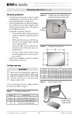
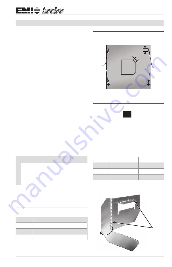
Ceiling cutout/rod placement 

Figure 6 

template (shipped with unit)

(51mm x 45°)

2.000 x 45° TYP

rod 

Positions

1.500 TYP

rod 

Positions

(38mm TYP)

Ceiling rod positions

Table 3 

Model

Dimension A 

Dimension B

9 & 12 

19 50” (495mm) 22 87” (581mm)

24 

29 19” (740mm) 30 80” (782mm)

36

29 19” (740mm) 43 06” (1094mm)

Mounting brackets

Figure 7 

Fold 

bracket along 

perforations

Содержание EMI America Series

Страница 1: ... CAHH12 CAHG18 CAHH18 CAHG24 CAHH24 Units 9 000 12 000 18 000 24 000 Btuh 2 6 3 5 5 3 7 0 kW Straight cooling only circuit load two circuits CACG 30 CACH 30 CACG 36 CACH 36 Units 30 000 36 000 Btuh 8 8 10 5 kW Installation Operationand Maintenance Manual ECR International LLC 5780 Success Drive Rome NY 13440 www enviromaster com An ISO 9001 2000 Certified Company CAHH12 ...

Страница 2: ...MI and ECR International and is tested and rated in accordance with AHRI Standard 210 240 and UL 1995 Due to ongoing product development product designs and specifications may change without notice Please contact the factory for more information Contents 2 Read Before Proceeding 3 Verify Unit Before Installing continued 6 Piston Orifice Replacement when required 7 Mounting the Unit 8 Condensate Pi...

Страница 3: ...sult in a fire explosion or electrical shockcausingpropertydamage personal injury or death Safety Instructions This manual is intended as an aid to quali fied service personnel for proper installa tion operation and maintenance of the EMIAmericaSeries highefficiencyevapo rator Read these instructions thoroughly andcarefullybeforeattemptinginstallation or operation Failure to follow these instructi...

Страница 4: ...ns contained in this document AllEMIairhandlersarebackedbyEnviro master International LLC and are tested rated and certified in accordance with ARI standards 210 240 and UL 1995 Verify Unit Before Installing Standard features CACG CAHG units G units require a remote thermostat for operation They do not include an onboard controller CACH CAHH units H units include an on board micropro cessor contro...

Страница 5: ...ice and use R410A refrigerant only Controls and Components factory installed or supplied Connections for 24V remote remote thermostat Customcontrolboardfeaturingprogram mability configuration and multiple modes of operation CACH CAHH only Controls also feature anti short cycle timer post purge fan relay and an on board 30 amp electric heat relay Condensate pump with 36 0 9 m lift measured from bas...

Страница 6: ...mpressor should the pump become blocked or fail Important Totalliftforthispumpis36 0 9 m or less Air vanes Air outlet vanes are manually adjustable on the models 9 and 12 or driven by an electric motor on the models 24 and 36 Wherefitted themotorizedairvanescan be set to auto sweep or can be stopped in a fixed position Heating The cassette may be fitted with electric heaters which are equipped wit...

Страница 7: ... a 4 in the capacity decoding field The piston will need replacement only on the 24 000 Btuh zone All other applications use the factory installed orifice Follow these instructions to replace the orifice BEFORE mounting the unit Replacing the piston orifice Disassemble the orifice joint remove the 1 factory installed orifice and replace with the orifice listed in Figure 1 supplied in the Kit Bag P...

Страница 8: ...3 8 3 4 NOTICE Piping may be roughed in before wall board or panels are placed in new con struction PVC pipe 3 or 4 I D may be used as a pipe chase Unpacking TheCassettefasciaandmainchassisarepack aged together for increased protection Remove the banding straps and lift the 1 cardboard lid Fascia is packed in bubble wrap and on 2 top of the chassis fascia is not attached to the chassis for shippin...

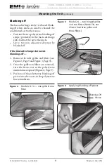
Страница 9: ...wo non adjacent sides may be blanked off If the fascia discharge slot needs blanking off Remove the inlet grilles and filters see 1 Figure 2 Page 9 and Figure 3 Page 9 Once the grilles and filters are removed 2 turn the fascia over so the polystyrene insulation is exposed Figure 4 Page 9 Push one of the polystyrene blanking off 3 pieces into the recess in the polystyrene fascia insulation Models 9...

Страница 10: ...reshouldbeaminimum1 25 4mm 8 clearance above the depth of the cassette and the false ceiling for proper instal lation See Figure 5 Page 10 See the cassette dimensions in the back of this manual for cabinet sizing Spacing requirements Figure 5 Dimension A 1 minimum space above the false ceiling for installation A A 1 Model Dimension A 9 12 11 84 0 3 m min 24 12 55 0 32 m min 36 14 51 0 37m min Remo...

Страница 11: ...dded bolts For previously built concrete slabs install hanging bolts with an expan sion anchor Follow local building codes for required safety cables braces etc Ceiling opening NOTICE Make sure the ceiling grid is supported separatelyfromtheCassette Theceiling mustnotbesupportedbyanypartofthe Cassette unit fascia or any associated wiring or pipe work Cut an opening in the false ceiling with the si...

Страница 12: ...s as shown in Figure 8 Page 12 Secure the unit in position with locknuts 6 and washers on either side of the cassette bracket Ensure threaded rod does not protrude 7 more than 2 51mm below the mount ing bracket see Figure 9 Page 12 NOTICE If the ceiling is not level or even it is important that the cassette is installed level to ensure correct pump operation and to maintain fan clearances Place a ...

Страница 13: ...s a check valve at the pump dis charge to prevent water from draining backintotheunit Thispipingtechnique will minimize any issues should the check valve become stuck open from airborne debris Condensate pipe work should slope 3 downwards in the direction of water flow with a minimum gradient of 1 per 10 8mm 1m There must be no uphill gradientsotherthaninthefirst36 0 9m of pipe work from the casse...

Страница 14: ...nockouts varies with unit size Branch duct knock outs are 5 133mm round Fresh air knockouts are 1 x2 32x64mm rectangular on models 9 12 3 76mm square on models 24 and 36 Cut the black insulation around the 2 knock out Figure 13 Page 14 Snip the tabs holding the knock out in 3 place Figure 13 Page 14 Remove the metal knock out and the 4 black insulation behind it Attach the duct collars field suppl...

Страница 15: ...id contact with sharp edges Wrap refrigeration valves with a wet rag heat sink to protect valves while brazing See Figure 16 Page 16 DONOTuseasuctionlinesizelarger than the condenser service valve con nection This can harm the compres sor Install a reducer when used only on the inside connection NOTICE ThecassetteisequippedwithaFloRater piston expansion device Connections are sweat type Piping con...

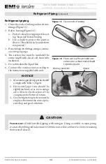
Страница 16: ...razetubingintofittings usingacontinu 3 ous nitrogen purge The suction line must be insulated the 4 entire length with closed cell foam tube insulation Do not insulate the liquid line 5 Connect the outdoor unit according to 6 the instructions supplied with unit NOTICE Maximumequivalentpiperunshould 1 comply with Table 1 Page 8 Horizontal pipe runs should be 2 slightly inclined so as to encourage oi...

Страница 17: ...igerant Add and 4 remove only liquid never vapor Chargetoproperweight chargebasedon 5 feet of interconnect Figure 19 Page 17 See tables on page 18 CAUTION Refer to the charts in the condenser manual to fine tune the refrigerant charge WLCG30utilizesaTXV thermoexpan sion valve which should be set at 15 F superheat CAUTION Charging should be done with a dial a charge or weighed in with a scale WARNI...

Страница 18: ...4 00 12 12 000 Btuh 25 oz 23 g m 35 S1CG3 CAC_36 25 oz 59 g m 97 50 18 18 000 Btuh 25 oz 59 g m 65 S1CG6 CAC_36 25 oz 59 g m 110 00 24 24 000 Btuh 25 oz 59 g m 63 S2CG S2HG R410A refrigerant charge table Table 5 Condenser Evaporator pairing Line charge per foot Factory charge Condenser Evaporator pairing Line charge per foot Factory charge S2CG99 S2HG99 2 CAH_09 25 oz ft 23 g m 40 40 51 51 S2CG92 ...

Страница 19: ...motor plug by plugging it into the socket connection on the chassis Ensure that the polarized connector a 2 position is in the proper orienta tion and connected Route the wires in a way that ensures b they won t become trapped cut bro ken or chaffed ONLY Cassette G models CACG 5 CAHG contain a second cable connec tion to the control box for the Infrared Unit Mount Control Ensure that the polarized...

Страница 20: ...ug into Figure 23 socket on chassis Female vane motor plug on chassis Male vane motor plug on fascia Connect infrared unit cable H Figure 24 units only Red stripe is conductor 1 polarized 10 position connector Secure fascia to chassis Figure 25 CAUTION DO NOT over tight en the bolts This could cause damage tothefasciaanddrain pan Adjust louver position to 30 Figure 26 from plumb ...

Страница 21: ...at cool thermostat Ifyouhaveselectedanoutdoorheatpump unitandanindoorunitwithelectricheat then chose a two stage heating single stage cooling thermostat Field supplied thermostats When selecting a thermostat other than one offered by EMI it is important to choose a 24V thermostat that matches your applica tion EMI equipment is compatible with most mercury bulb digital or power stealing ther mostat...

Страница 22: ...mum load current under non fault conditions at the stipulated voltages Avoid large voltage drops on cable runs 3 particularly in low voltage wiring The correct cable size must be used to 4 ensure a voltage drop of less than 1 volt in the control wiring Once the refrigeration pipe work is 5 complete the electrical supply can be connected Low voltage wiring must be at least 6 18 awg Connect wiring T...

Страница 23: ...st 18 AWG The24Vcontroltransformerislocatedin 1 theevaporator Thisprovideslow voltage controlpowertoboththeevaporatorand condenser Depending on the models selected the low voltage interconnect control wiring may be different Refer to the wiring diagram to connect 2 the low voltage wiring to the appropriate terminals Once the connections are made replace 3 control box cover with the wiring dia gram...

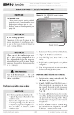
Страница 24: ...e proceeding Perform complete inspection NOTICE To perform a system electrical check Turn off all power to the indoor and outdoor units Isolate the compressor to prevent it from operating until the check is completed by removing the con nection at the Y terminal on the outdoor unit Remove any tools or other obstructions 1 Inspect all electrical connections 2 Separate any lines that contact each 3 ...

Страница 25: ...rge louvers are correctly positioned NOTICE Theunitisequippedwithasafetyswitch that will activate the pump when the condensate reaches a critical level The safety switch will also de energize the compressor if the water level becomes too high Check cooling operation Cooling onlysystems Turnthesystem 1 power on and turn down the system set point to activate the compressor Check heat pump operation ...

Страница 26: ...ycle with the call for heating or cooling CACH CAHH units only The indoor unit utilizes a two speed motor For Remote Thermostat Operation fan speed selection can be made through the DIP switch settings located on the main control board By set ting DIP switch 3 Remote Thermostat Fan Speed Selection to ON the fan speed will be set to High Switching to OFF the fan speed is set to Low COOLING operatio...

Страница 27: ...ection Optional Heat pump with Electric heat Two stage heating For remote thermostat operation for two stage heating including a heat pump con denser and indoor electric heat the control must first be configured properly Remote Thermostat ON heat source ON See Fig ure 36 Page 35 Theremotethermostatwillcontrolthecallfor electricheatoperation onoroff throughthe low voltageterminals RandW andcompres ...

Страница 28: ...nit mounted display Turn on power to the indoor unit so the 3 controller can be operated Press and hold both the MODE and 4 PROGRAM buttons on the remote for 5 seconds to enter Configuration mode as shown in Figure 35 Page 34 Configure the controller using 5 Figure 36 Page 35 After the configuration is completed 6 pointtheremoteatthecassetteunit sdis play Then press and hold the POWER NOTICE To te...

Страница 29: ...ol setpoint above 3 room temperature Verify that the compressor shuts down 4 Wait for the blower post purge to com 5 plete Then verify that the system shuts down properly Be sure to return DIP switch 1 Test 6 mode to OFF before leaving the sys tem Verify cooling only operation This arrangement uses a cooling only 1 outdoor unit with no heat source in the cassette indoor unit The configuration 2 Fi...

Страница 30: ...ure at the cassette unit The compressor should come on Verify 5 that supply air is cooler than room air Usetheremotetoadjustsetpointtemper 6 ature1 Fabovetheroomtemperature at the cassette unit or just enough needed to activate first stage heating The compressor should come on 7 Verify that supply air is warmer than 8 room air Increase the setpoint until the second 9 stage heating electric heaters...

Страница 31: ...roller Overview AmericaSeries unit mounted microprocessor controller control panel Figure 33 Dip switches Control panel WARNING Electrical shock hazard Before removing the control box cover make sure that all power is re moved from both the indoor cas sette unit and outdoor condenser unit Failure to comply could result in severe personal injury or death ...

Страница 32: ...ly in Test mode This will damage the compressor DO NOT leave the unit in Test mode after setup Return dip switch 1 to the OFF position for normal operation OFF OFF Disables Test mode 2 Louver oscillation for remote thermostat mode only On If DIP Switch 4 is ON enables louver oscillation during operation OFF Off If DIP Switch 4 is ON disables louver oscillation during operation 3 Fan speed setting ...

Страница 33: ...r off 2 Power LED In Remote Thermostat mode on when power is applied to the unit In Hand Held Controller mode on while the cassette unit is in the ON mode off while unit is in the OFF mode 3 Cooling LED On when the unit is in cooling operation 4 Heating LED On during calls for heat 5 Timer Alarm LED On steady while the unit is in Sleep Timer mode flashes to indicate fault codes 6 Clear Filter warn...

Страница 34: ... temperature Configuration Set Time or Programming mode press to increase the setting DOWN Normal operation press to decrease the setpoint temperature Configuration Set Time or Programming mode press to decrease the setting FAN Press to toggle between fan modes High Low or Auto PROGRAM Normal operation Press to toggle between manual operation and Pre programmed 7 day run mode Configuration Set Tim...

Страница 35: ...ation and connected to an appropriate compressor unit Auto changeover differential see Note 2 04 d b x 2 6 2 Auto changeover automatically operates the unit in heating or cooling based on room temperature versus setpoint This setting is the dead band temperature Cooling is on while room temperature is at setpoint PLUS dead band Heating is on while room temperature is at setpoint MINUS dead band Ex...

Страница 36: ...7 Day programming use Table 7 Page 37 to record settings Day of week Mon Tue Wed Thu Fri Sat Sun The louver is closed when the fan is off Period of day Morning Day Evening Night The periods provide four time settings to initiate a change in cooling heating setpoints They allow adjustments for setback such as night setback daytime setback and occupied settings for residential applications Set the h...

Страница 37: ... using 7 day programming Table 7 Night Cool Heat Auto Evening Cool Heat Auto Day Cool Heat Auto Morning Cool Heat Auto Time Temp Time Temp Time Temp Time Temp Time Temp Time Temp Time Temp Monday Tuesday Wednesday Thursday Friday Saturday Sunday To copy the settings from any day to the entire week 1 Select the day to be copied 2 Simultaneously press the Fan and Prog buttons for three seconds ...

Страница 38: ...mode This can happen if commands are entered into the remote but it is not pointed at the cassette To re synchronize Enter any command into the remote while pointing it at the cassette s infrared receiver window Alternatively hold the POWER SEND buttonfortwoseconds Alloftheoptional remote ssettingswillbetransmittedtothe cassette The cassette will respond with a beep indicating that it has successf...

Страница 39: ...de In Fan mode either HIGH or LOW will appear on the LCD Fan Operation The indoor unit utilizes a two speed motor with three operational fan modes High Low and Auto The FAN button will allow the selection of the desired fan setting in all modes except Dry mode In Dry mode the fan will operate constantly at low speed The LCD will indicate the fan speed selection High and Low are constant fan settin...

Страница 40: ...he cooling has cycled off or fol lowing a power outage the compressor will not restart for at least three minutes anti short cycle timer Heating mode Optional Electric heat operation Air Conditioning unit outdoors For operation with electric heat the control mustfirstbeconfiguredproperly Heatsource ON Heat pump OFF See Figure 36 Page 35 For electric heat operation first turn the unit on via the PO...

Страница 41: ...pired the compressor will switch off The fan will operate as described in Fan 9 Operation Optional Heat pump with Electric heat 2 stage heating For heat pump operation with electric heat the control must first be configured properly Heat source ON Heat pump ON See Figure 36 Page 35 For heat pump operation with optional elec tric heat turn the unit on via the POWER SEND button ThenselectHeatingmode...

Страница 42: ...temperature is greater than 7 the setpoint temperature by more than two degrees the unit will run Cooling mode constantly If the room temperature is within two 8 degrees of setpoint the unit will cycle cooling on seven minutes and off seven minutes to remove humidity from the air while not over cooling the room If the room temperature is less than the 9 setpoint temperature by more than two degree...

Страница 43: ...When the PROGRAM 2 CLOCK buttons are pressed simultane ouslyagainorleftidlefortwentyseconds the control will save the new settings and return to the previous interface mode While in the 7 Day Programming mode 3 the words 7 DAY PROGRAM are dis played on the LCD Use the UP or DOWN ARROW buttons 4 tochangethetime temperatureorperiod settings Use the 5 CLOCK or PROGRAM buttons to select the mode to be...

Страница 44: ...ay Programming mode Clean Filter Alarm To aid in filter maintenance the cassette con troller will indicate when a scheduled filter cleaning is required by flashing the Timer Alarm LED During normal operation the microprocessor will keep track of the units run time When the clean filter time has elapsed 1 the Timer Alarm LED will flash four times to indicate that the filter needs to be cleaned The ...

Страница 45: ...d 2 the call for heating or cooling has been removed the indoor fan will remain on for an additional sixty 60 seconds This increasesefficiencybypullingtheremain ing energy from the unit Some thermostats are equipped with an AUTO ON fan switch When this switch is placed in the ON position the fan will run continuous WhentheswitchisintheAUTO position the fan will cycle with the call for heating or c...

Страница 46: ...ch in Heating mode Adjustthesetpointtemperatureabovethe 8 room temperature The compressor and fan motors will start 9 and heating will begin Depending on the thermostat selected 10 electric heat will also energize when the deviation between room temperature and setpoint temperature is high enough to call for second stage heating See the thermostat owner s manual for this feature Place the setpoint...

Страница 47: ...an be set in the Configuration By selecting OFF the backlight will re main off at all times ByselectingON thebacklightwillremain on at all times including while in the Off mode interface If Intermittent is selected the backlight will remain for 10 seconds after the push of any button while the control is in the On mode or after the push of the ON OFF button while in the Off mode interface Drain Pa...

Страница 48: ...eze condition is detected continuously for three 3 minutes the Timer Alarm LED will flash three 3 times to signify that a fault has occurred The compressor will switch off for a minimum of three 3 minutes AND until the fault condition is corrected Also if the microprocessor detects an evaporator freeze condi tion four 4 times within a 24 hour period the clean filter indicator will appear 4 Clean f...

Страница 49: ...nd lifting to clear the retaining clips Figure 39 Page 49 Lift the filter off the grille Place filter c onaflatsurfaceandvacuumanyaway dust and debris vacuum all filters and grills Also vacuum any acces sible parts on the unit Figure 40 Page 49 Or use a garden hose d Wash the grille and filter with a hose Let filters and grilles dry before replacing Replace filters clips and front grille e before ...

Страница 50: ...e with EMI America Series condensers The air handle indoor unit and con denser outdoor unit must be indepen dently connected to the electrical service panel and protected by separate time delay fuse or HACR breakers See the unit name plate for the correct breaker type and size The indoor and outdoor units are also connected to each other via a 24V inter connect wiring Figure 42 Page 51 or Figure 4...

Страница 51: ...anual P N 240007756 Rev A 051509 51 Made in the USA Troubleshooting General continued Models CACG CAHG Low voltage interconnections remote thermostat Figure 42 operation Models CACH CAHH Low voltage interconnections with without optional Figure 43 remote thermostat operation ...

Страница 52: ...ls Y and C of the outdoor unit Y1 and C of the cassette G and C of the cassette fan signal Heat pump units Heatpumpunitsrequire18AWGlow voltage interconnectingwirebetweentheindoorand outdoor units Also interconnect wiring is requiredbetweentheindoorunitandremote thermostat Refertolow voltageinterconnect diagram Figure 42 Page 51 for low voltage connections The wall mounted thermostat will switch t...

Страница 53: ...fect the amp draw of the heater 5kw 22 7 A 3kw 13 6 A 1 5kw 6 9 A Theelectricheatrelaycanalsobeverified 4 by placing a voltmeter across the high voltage relay output terminal and the incoming power L2 terminal Iftheunitisworkingcorrectly thereading 5 shouldbethesameasmeasuredacrossthe incoming power supply As a safety feature an auto reset limit switch is located on the heater assembly The limit w...

Страница 54: ...heck for a low voltage signal place a voltmeter across terminals Y and C of the outdoor unit Y1 and C of the cassette When the unit is working correctly there should be a reading of 24 Vac Next place the setpoint further above room temperature to activate second stage heat ing Electric heat will energize along with 1 the compressor when the deviation between room temperature and setpoint temperatu...

Страница 55: ... temperature is satisfied there will be a three minute delay before the out door unit is allowed to restart The cassette controller or remote thermostat will also control the indoor fan by switching high voltage power to the fan motor with the fan relay When energized high voltage power can be measured between the relay output and the L2 terminal of the incoming power supply For optional remote th...

Страница 56: ...mer one must be removed from the system Q The condenser will not start although the indoor unit appears normal What should I do A Attheindoorthermostat makesurethat thecontrolisincoolingandthesetpoint temperatureisbelowroomtemperature Next using a Voltmeter check for 24V across the yellow Y and brown C wires If 24V is present then check for wiring breaks or improper connections between the indoor ...

Страница 57: ...en check the following Check that the freeze sensor inserted fully and snug in the coil fins If not another location may need to be selected Be careful not to insert the sensor directly into the coil tube rather insert the sensor between two tubes Check the indoor air filter It should be clean and free of dirt A dirty filter will reduce airflow and efficiency Alsocheckthatthecoilisclean Ifthe coil...

Страница 58: ...CE Due to ongoing product development designs specifications and performance are subject to change without notice Please consult the factory for further information Features 1 Optional discharge knockouts 5 inch diameter 3 available 2 Fresh air inlet knockouts 1 x 2 inches 2 available 3 Condensate dis charge inch diameter 4 Suction connection inch diameter 5 Liquid connection inch diameter 6 Conde...

Страница 59: ...8 90 226 8 90 226 J ref 2 67 68 3 38 86 3 38 86 K 25 86 657 35 61 904 47 78 1214 L 12 76 324 18 69 475 24 73 628 M 1 73 44 1 97 50 1 97 50 N ref 2 16 55 2 72 69 2 72 69 O 5 12 130 5 12 130 5 12 130 P ref 11 34 288 12 05 306 14 01 356 R typical 1 50 38 1 63 41 1 63 41 R1 19 50 495 29 19 741 29 19 741 R2 23 27 591 31 20 792 42 66 1084 R3 22 47 571 30 41 772 43 45 1104 S 7 19 183 6 87 174 6 87 174 T ...

Страница 60: ...erant Type R410A CONNECTIONS Model 9 12 24 36 Suction Liquid 3 8 3 8 Condensate Drain I D I D I D Branch Duct 5 Ø 5 Ø 5 Ø Fresh Air Duct 1 x 2 3 x 3 3 x 3 FILTRATION Model 9 12 24 36 Type Washable Mesh Quantity 1 2 3 Efficiency 80 CONDENSATE PUMP Model 9 12 24 36 Maximum Head 36 0 9 m Min Flow Rate 2 5 GPH 9 5 l h Must bush down to 5 8 interconnect for 18K system Measured from bottom of unit Disch...

Страница 61: ...A S1C6000 CAC_36 36 000 13 0 0 72 11 5 R410A S2C9900 2 CAH_09 18 000 13 0 0 75 11 5 R410A S2C2200 2 CAH_12 24 000 13 0 0 75 11 5 R410A S2C9200 1 CAH_09 1 CAH_12 21 000 13 0 0 75 11 5 R410A Heat pump systems Table 14 CAH_ refers to CAHG CAHH Condenser Cassette Cooling Btuh Heating Btuh SEER HSPF SHR EER COP Ref S1H9000 CAH_09 9 000 8 200 13 0 7 7 0 74 11 8 3 2 R410A S1H2000 CAH_12 11 600 10 600 13 ...

Страница 62: ...12 40 500 13 0 0 0 75 11 5 R410A System options with T2H T3H or T4H top discharge Table 16 Condenser Cassette Cooling Btuh Heating Btuh SEER HSPF SHR EER COP Ref T2H8800 2 CAH_24 36 000 26 400 13 0 7 7 0 75 11 5 3 0 R410A T2H8400 2 CAH_24 42 000 32 600 13 0 7 7 0 75 11 5 3 0 R410A T2H4400 2 CAH_24 48 000 40 000 13 0 7 7 0 75 11 5 3 0 R410A T2H9800 1 CAH_12 1 CAH_24 27 200 21 200 13 0 7 7 0 75 11 5...

Страница 63: ... ID Fan Motor Volts ID Fan Motor Amps Total Volts Total Amps Temperatures Degrees F Compressor Suction Compressor Discharge Liquid Out Cond Liquid before Expansion Suction out Evaporator Capacity Calculations DB Temp Split at Evaporator Test Summary Compressor Superheat Sub Cooling Test Unit Performance Data Sheet NOTICE The Test Unit Performance Data sheet is provided for use by a qualified servi...

Страница 64: ...MI s Product Line Indoor Units Outdoor Units S1CG S1HG Single Zone Side Discharge S2CG S2HG Dual Zone Side Discharge WLCG WLHG High Wall Air Handler UNCG UNHG Universal Floor or Ceiling Air Handler CACG CAHG Cassette Air Handler T2CG T3CG and T4CG 2 3 and 4 Zone Top Discharge ...

Отзывы: