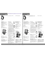
Model FC3JU
Model FC3JU
INSTALLATION
For 2-speed ECM WHFs, the yellow wire is not used and
should be cut off at the PC board. Use wire nuts to connect the
FC3JU wires to the WHF wires and the incoming 120VAC
power wires. Orient the FC3JU and electrical box as shown.
Use wire nuts to connect the FC3JU wires to the WHF wires
and the incoming 120VAC power wires. Orient the FC3JU and
electrical box as shown.
Electrical box on WHF
Electrical box on WHF
Ground
screw
Ground
screw
Power
Cord or
Romex
Power
Cord or
Romex
POW
E
R
POW
E
R
WH
F
Wiring FC3JU to 2-Speed ECM WHF
Wiring FC3JU to 3-Speed ECM WHF
The WT3 and FC3JU are connected using the 25-foot
RJ11 cable provided. One end of the cable should
already be connected to the WT3. Plug the other end of
the cable into the FC3JU.
Connect the WT3 to the FC3JU
3)
WHF High Speed
WHF High Speed
WHF Low Speed
WHF Low Speed
WHF ed Speed
Connects
Connects
Not Used.
WHF Neutral and
WHF Neutral and
120VAC Neutral
120VAC Neutral
WHF Ground and
WHF Ground and
Power Ground
Power Ground
Power 120VAC
Power 120VAC
High Speed (Purple)
High Speed (Purple)
FC3JU Wire
FC3JU Wire
Low Speed (Red)
Low Speed (Red)
Med Speed (Yellow)
Med Speed (Yellow)
Neutral (White)
Neutral (White)
Ground (Green)
Ground (Green)
120VAC (Black)
120VAC (Black)
Find a suitable location for the wall timer, typically in the
bedroom area. Run the low voltage plug&play cable to
the wall timer location and connect to the WT3.
Install the WT3 Wall Timer
2)
The WT3 can be installed in a
single gang box or directly to
the wall using the hardware
provided.
WT3
Timer/Speed
Control
Wall anchors
25-foot P&P
Cable supplied.
An extension cable, Model
PNP25C, is available if you
need more than 25’ length.
FC3JU
Fan Control
Wall anchors
1-Gang Box
on WHF
25-foot P&P
Cable supplied
Use template
in Manual
as guide
WT3
Timer/Speed
Control
WH
F
POW
E
R
WH
F
WH
F
POW
E
R
6


