ETS 73
0548-990-51---60g_2019.10.indd
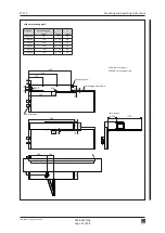
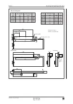
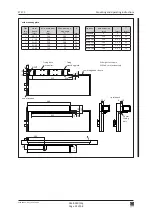
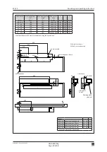
217
424
650
358
45
76
17*
53**
689
60
0...250
~398
280
100
60
120
45
95
75
170
M6
24
23
26
Ø20
z
10
67
8
0548-990/52g
Page 34 of 98
Mounting and operating instructions
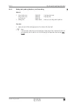
4.5
Rod assemblies stainless steel
4.5.1
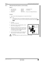
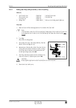
Normal rods pushing function / Lintel mounting
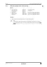
Material:
1 Drive mechanism
0548-030
Covering aluminium
Drive mechanism
0548-031
Covering inox
incl. fixing set
0548-107
1 Normal rods
0548-104
Normal rods KTL
0548-104/01
Procedure:
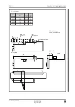
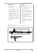
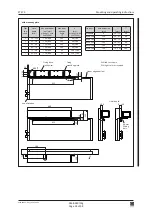
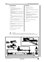
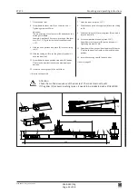
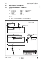
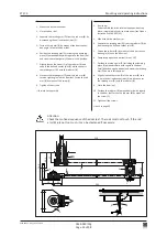
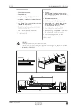
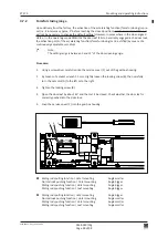
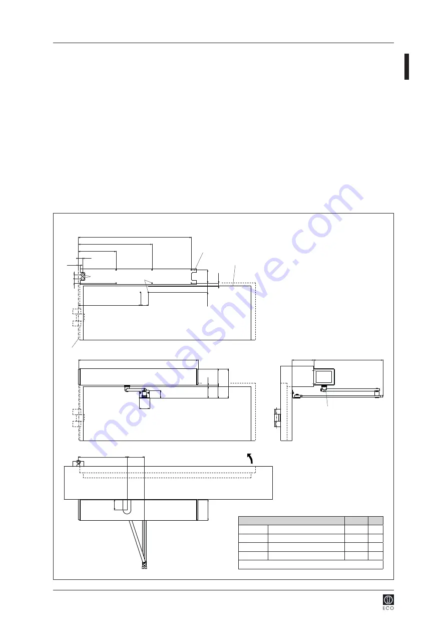
1. Mark out and drill the fastening holes on the lintel and the door leaf.
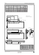
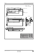
DIN right = as shown
DIN left = mirror-inverted
Chassis profile
Lintel depth
Lower edge door frame
Clamping piece stan
-
dard
Axis of rotation
Options
*
**
0548-114
Clamping piece standard
10...22
53
0548-124
Clamping piece -13 mm
10...12
40
0548-125
Clamping piece +20 mm
10...42
73
0548-126
Clamping piece +50 mm
10...72 103
adjust the dimensions accordingly


