background image

30 

C H A P T E R   3   I N S TA L L I N G   D R I V E R S   A N D   S O F T W A R E

Intel Chipset Driver

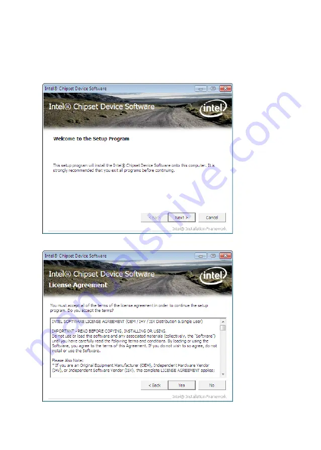
The Intel Chipset Device Software updates the Windows XP/7 INF files so that the Intel chipset is correctly 

configured. Follow these instructions to install the chipset software :

1.  Browse to the \DRIVER\chipset\Intel\Inf folder.
2.  Double-click setup.exe. The following screen appears. Click 

Next

 to continue.

3.  Read the license agreement, then click 

Yes

.

Содержание EC-1559

Страница 1: ...POS Terminal EC 1559 Service Manual...

Страница 2: ......

Страница 3: ...radiate radio frequency energy and if not installed and used in accordance with the instructions may cause harmful interference to radio communications However there is no guarantee that interference...

Страница 4: ...lity Chapter 3 Installing Drivers and Software This chapter provides information for installing drivers Chapter 4 Locating the Problem Refer to this chapter to locate the failing part or cause of the...

Страница 5: ...3 Super IO Configuration 14 Serial Port x Configuration 15 Parallel Port Configuration 16 H W Monitor 17 CPU PPM Configuration 18 Chipset Settings 19 System Agent SA Configuration 19 PCH IO Configurat...

Страница 6: ...49 Inverter connectors 49 CHAPTER 5 REPLACING FIELD REPLACEABLE UNITS FRUs 51 Safety and precautions 51 Before you begin 52 Replacing parts 52 HDD 53 IO Panel Cover 54 Stand Base Back Cover 54 Stand B...

Страница 7: ...guration sub menu 16 Figure 2 11 Hardware Monitor sub menu 17 Figure 2 12 CPU PPM Configuration sub menu 18 Figure 2 13 Chipset Settings Screen 19 Figure 2 14 System Agent SA Configuration sub menu 19...

Страница 8: ...vi...

Страница 9: ...ing the machine on page 1 Identifying components on page 2 Unpacking the machine It is a good idea to save the packaging materials and shipping box in case that machine needs to be returned for servic...

Страница 10: ...ying components This section describes the parts and connectors on the machine Front right view 1 2 Figure 1 2 Front right view Component Description 1 15 inch TFT LCD 2 LED Power Indicator HDD Indica...

Страница 11: ...3 Rear view 1 2 4 3 5 Figure 1 3 Rear view Component Description 1 MSR optional Slot 2 VFD Customer Display optional Slot 3 Cable Compartment 4 HDD Compartment 5 Cable Compartment Cover...

Страница 12: ...I O connectors 6 3 2 1 4 5 7 8 9 10 11 12 Connector Description 1 COM 4 port 2 VGA port 3 COM 1 port 4 USB ports 5 RJ 11 cash drawer port 6 DC 12V input connector 7 PS 2 port 8 COM 3 port 9 COM 2 por...

Страница 13: ...s on page 25 Security Settings on page 26 Save Exit on page 27 About the Setup Utility The BIOS Setup Utility enables you to configure the following items Hard drives diskette drives and peripherals V...

Страница 14: ...DEL to run Setup Press the delete key Delete to access the BIOS Setup Utility BIOS navigation keys The BIOS navigation keys are listed below Key Function Moves between the available menus Moves the c...

Страница 15: ...the highlight to other options When an option is highlighted execute the option by pressing Enter Some options lead to pop up dialog boxes that prompt you to verify that you wish to execute that optio...

Страница 16: ...or System memory System Time and System Date System Time System Date The System Time and System Date items show the current date and time held by the machine To set the time and date use the Tab key t...

Страница 17: ...ings This setup screen includes sub menus for APCI Configuration CPU Configuration SATA Configuration USB Configurations Super IO Configurations and Hardware Health Configuration Figure 2 3 Advanced S...

Страница 18: ...re power down the system can be resumed by Wake Up Alarms This item lets you install a software power down that is controlled by the normal power button on your system If the item is set to Instant Of...

Страница 19: ...protect certain system memory data regions from insertion and execution of potentially harmful code Intel Virtualization Technology This feature allows you to enable or disable Intel Virtualization T...

Страница 20: ...Legacy Native Mode Selection This item allows you to select IDE mode Select Legacy mode for old OS such as Windows 98 2000 Select Native mode for Windows XP and later version SMART Self Test This item...

Страница 21: ...ecific the USB transfer timeout value for control bulk and interrupt transfers Device reset time out This item allows you to specific the timeout periods for USB device initialization and the Start Un...

Страница 22: ...item allows you to determine the functional degree of Watch Dog Watch Dog Timer When select any time period the Watchdog Timer will be enabled after that time period passes every time the system boot...

Страница 23: ...nfiguration Figure 2 9 Serial Port x Configuration sub menu Serial Port x This item allows you to enables or disables a serial port Change Settings This item allows you to specific IO address and IRQ...

Страница 24: ...port Device Mode This item allows you to set the data transfer protocol for the parallel port There are four options Standard Parallel Port Mode EPP Mode Enhanced Parallel Port ECP Mode Extended Capab...

Страница 25: ...r Figure 2 11 Hardware Monitor sub menu Shutdown Temperature This item allows setting the shutdown temperature Once enabled the machine will automatically shutdown when the temperature reaches the lim...

Страница 26: ...Speedstep Technology When enabled CPU will reduce power consumption CPU C3 Report This item is used to enable or disable CPU C3 report to OS CPU C6 Report This item is used to enable or disable CPU C...

Страница 27: ...19 Chipset Settings This screen allow you to configure the chipset options Figure 2 13 Chipset Settings Screen System Agent SA Configuration Figure 2 14 System Agent SA Configuration sub menu...

Страница 28: ...I Express Port This item allows you to enable or disable the Mini PCI Express device ASPM This item is used to select the level of PCI Express Active State Power Management PCIe Speed This item is use...

Страница 29: ...21 USB Configuration Figure 2 16 USB Configuration sub menu EHCI1 EHCI2 These item allow you to enable or disable USB 2 0 support...

Страница 30: ...mory address space Host cycles that hit the aperture range are forwarded to the graphics chip without any translation DVMT Pre Allocated This item allows you to adjust system memory that can be pre al...

Страница 31: ...ll maintain the original aspect ratio of the chosen resolution and display it with black bars to the sides above below the on screen image as required LVDS Backlight This feature allows you to adjust...

Страница 32: ...system memory Max TOLUD This field allows you to select the maximum value of TOLUD Dynamic assignment would adjust TOLUD automatically based on largest MMIO length of installed graphic controller MRC...

Страница 33: ...is item is used to select the Power on state for Numlock Full Logo Screen display This item enables you to show the full screen logo on the bootup screen Option ROM Messages This item allows you to se...

Страница 34: ...r User Password on the Security menu and press Enter 2 The password dialog box appears 3 If you are creating a new password type in the password You can type alphanumeric characters Symbols are ignore...

Страница 35: ...xit or press No to return to the menu Restore Defaults This option opens a dialog box that lets you load optimized defaults for all appropriate items in the Setup Utility The optimized defaults place...

Страница 36: ...28 C H A P T E R 2 B I O S S E T U P...

Страница 37: ...page 30 Intel Chipset Graphics Driver on the page 32 LAN Driver on the page 34 Touch Screen Driver on the page 36 Driver auto installation Use an external CD ROM drive to install the drivers or copy t...

Страница 38: ...Software updates the Windows XP 7 INF files so that the Intel chipset is correctly configured Follow these instructions to install the chipset software 1 Browse to the DRIVER chipset Intel Inf folder...

Страница 39: ...ReadMe Information then click Next 5 The Intel Chipset Software Utility files are installed to the system When prompted to restart select Yes I want to restart my computer now Then click Finish to res...

Страница 40: ...Graphics Driver This utility installs the Intel Extreme Graphics 2 drivers for Windows XP 2000 To install the drivers 1 Browse to the DRIVER VGA intel folder 2 Double click the executable file The fol...

Страница 41: ...33 4 Browse the ReadMe Information then click Next 5 When installation is completed select Yes I want to restart my computer now Then click Finish to restart the system...

Страница 42: ...R E LAN Driver The network driver support Windows XP 2000 Refer to the following to install the drivers 1 Browse to the DRIVER LAN RealTek folder 2 Double click the executable file The following scree...

Страница 43: ...35 4 When installation is completed click Finish...

Страница 44: ...Driver Refer to the following to install the touch screen driver 1 Browse to the DRIVER Touch eGalax folder 2 Double click setup exe The following screen appears Click Next to continue 3 Read the lic...

Страница 45: ...the box for Install PS 2 interface drive and then click Next to continue 5 System will give you a warning click OK to continue 6 Uncheck the box for Install RS232 interface drive and then click Next t...

Страница 46: ...N G D R I V E R S A N D S O F T W A R E 7 Check the box for None and then click Next to continue 8 System will give you a warning click OK to continue 9 Uncheck the box for Support Mulit Monitor Syste...

Страница 47: ...39 10 Click Next to continue 11 Click Next to continue...

Страница 48: ...40 C H A P T E R 3 I N S TA L L I N G D R I V E R S A N D S O F T W A R E 12 Click Next to continue 13 Click Yes I want to restart my computer now and then click Finish...

Страница 49: ...he TouchKit application 1 Launch the TouchKit application from the Windows desktop by clicking on Start All Programs eGalaxTouch Configure Utility 2 Select the Tools page 3 Click the 4 Points Calibrat...

Страница 50: ...42 C H A P T E R 3 I N S TA L L I N G D R I V E R S A N D S O F T W A R E 5 Click OK to complete the 4 points calibration You may also use this application to adjust the touch settings NOTE...

Страница 51: ...age 49 Inverter connectors on the page 49 General checkout guidelines Use the following procedure to troubleshoot problems Identify as many symptoms as possible in detail Verify symptoms by recreating...

Страница 52: ...Status port 53A 10 High 1 Close Low 0 Open LCD symptoms Symptom Corrective Procedure LCD backlight is not working but text is still visible on screen 1 Reseat the LCD cable 2 Reseat the inverter cabl...

Страница 53: ...Procedure Power shuts down unexpectedly Cannot turn the system on 1 Reseat the power AC adapter cable 2 Reseat the power AC adapter 3 Replace the mainboard Cannot turn the system off 1 Hold down the p...

Страница 54: ...eripheral device symptoms Symptom Corrective Procedure USB ports do not work COM ports do not work 1 Reseat the I O cable 2 Reinstall the drivers 3 Replace the mainboard Boot symptoms Symptom Correcti...

Страница 55: ...1 JP2 JP3 1 1 5 5 2 2 6 6 Jumper Setting Description JLV1 LCD Backlight Inverter Power Select Jumper 1 2 Closed 5V 2 3 Closed 12V JLV2 LCD Panel Power Select Jumper 1 2 Closed 3 3V 2 3 Closed 5V JLV3...

Страница 56: ...iption JP2 COM3 Power Select Jumper 1 2 Close 5V 3 4 Close RING 5 6 Close 12V JP3 COM4 Power Select Jumper 1 2 Close 5V 3 4 Close RING 5 6 Close 12V JCMOS1 Clear CMOS Jumper 1 2 Close Keep Data 2 3 Cl...

Страница 57: ...connectors Mainboard connectors connector to inverter connector to LCD panel connector to customer display connector to MSR connector to SATA HDD connector to HDD power connector to speaker connector...

Страница 58: ...50 C H A P T E R 4 L O C AT I N G T H E P R O B L E M...

Страница 59: ...rsonnel should perform repairs on the EC 1559 Damage due to unauthorized servicing is not covered by the warranty Safety and precautions Computer components and electronic circuit boards can be damage...

Страница 60: ...prevent you from accidentally damaging the internal components Most of the electrical and mechanical connections can be disconnected by using your fingers It is recommended that you do not use needle...

Страница 61: ...ard drive compartment cover and slide the cover to the right as it shown on the picture 4 Remove the screw from the hard drive tray 5 Slide the hard drive disk up as it shown on the picture 6 Remove t...

Страница 62: ...L D R E P L A C E A B L E U N I T S F R U s IO Panel Cover 1 Flip up the LCD panel 2 Remove two screws from the IO panel cover and remove the cover Stand Base Back Cover 1 Rotate the LCD forward to t...

Страница 63: ...5 Stand Base Before proceeding remove the fol lowing FRUs IO Panel Cover on page 54 1 Flip up the LCD panel 2 Remove the screw from the IO panel 3 Position the EC 1559 as shown 4 Remove the stand base...

Страница 64: ...R 5 R E P L A C I N G F I E L D R E P L A C E A B L E U N I T S F R U s Back Cover 1 Remove the screw from VFD slot cover 2 Remove the VFD slot cover 3 Remove all screws from the back cover 4 Remove...

Страница 65: ...and chip If the thermal pads damaged replace them When replace the back cover the two standoff screws must be installed as shown below Tighten both of the screws until they resist and stop Thermal pad...

Страница 66: ...R U s Power Button Before proceeding remove the following FRUs Back Cover on page 56 1 Remove two screws 2 Remove the power button COM4 port and PS 2 Port Before proceeding remove the following FRUs...

Страница 67: ...on page 56 COM4 port and PS 2 port on page 58 1 Remove all screws from the I O panel 2 Remove four screws from the I O shield 3 Remove the I O shield Memory Before proceeding remove the following FRUs...

Страница 68: ...ng remove the following FRUs Back Cover on page 56 1 Open the hock 2 Pull out the battery Mainboard Before proceeding remove the following FRUs Back Cover on page 56 COM4 port and PS 2 port on page 58...

Страница 69: ...following FRUs Back Cover on page 56 1 Remove five screws 2 Remove the inverter cover 3 Remove three screws 4 Remove all cables from the inverter 5 Remove the inverter When replacing Put the inverter...

Страница 70: ...n page 61 1 Remove four screws 2 Remove the panel bracket Waterproof Seal Touch Panel Touch Cover LCD Panel Before proceeding remove the following FRUs Back Cover on page 56 Speaker on page 65 Power B...

Страница 71: ...63 APPENDIX PART LIST AND SPECIFICATION Figure 6 1 Exploded diagram main parts...

Страница 72: ...64 A P P E N D I X Figure 6 2 Exploded peripheral parts...

Страница 73: ...racket 21004500S0006 27 Hinge Mount Cover 2500350470300 28 Hinge Left 2108100000025 29 Stand base cover 2500250470300 30 Cuscapi Logo 2507450470000 NO DESCRIPTION ITEM NO 31 Hinge right 2108100000024...

Страница 74: ...ar I O COM1 2 powered with DC 0 5 12v BIOS selection COM3 4 powered with DC 0 5 12v Jumper selection 1 DB 15 VGA port 1 RJ11 port supports 2 cash drawer DC 24v 1 DB 25 for LPT port 1 PS 2 KB 1 RJ 45 L...

Отзывы: