background image

7

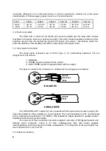
The 'SIGNAL OUTPUT' section on the back panel is provided with Speak-on connectors

(11).

To operate the amplifier on BRIDGED mode, place the 'OP. MODE' switch (8) to the

“BRIDGED” position. The correspondent Led on the front panel will shine. The input signal must be
connected to the channel I “BRIDGED INPUT” connector while the output signal will be present on
the central Speak-on connector labelled as “BRIDGED”. Remember that the BRIDGE mode is not
available on the PAM2000/2600 models.

The phase shifter used for BRIDGED mode is electronic and is placed in the input circuit,

thus lessening the distortion and increasing the phase margin. When operating on BRIDGED
mode, the signal input is made through channel I input and the corresponding input attenuator is
operative while the one of the other channel is not.

The cable between the amplifier outputs and the loudspeakers must be of good quality,

enough section and as short as possible. This is very important when the distance is long and the
load is low (4-8

). We recommend a section of 2.5mm

2

 or more for distances up to 10m and a

section of 4 or 6mm

2

 for longer distances. An easy way to known the required section, assuming a

4% loss, is:

Length in meters

Section in mm

2

=



Loudspeaker impedance in 

4. OPERATION

4.1. Starting up

To start up the amplifier turn on the 'POWER' switch (7). It will shine together with the two

red 'PROTECT' leds (5). After a while, the loudspeaker protection relays will close and the
PROTECT leds will be off.

It is very important to start the audio chain in the following order: sound signals , mixer,

equalizers or active filters and, finally, power amplifiers. To stop the chain follow the inverse order.

4.2. Input attenuators

They are based on step-rotative potentiometers placed on the front panel (1). The

attenuators make possible to use loudspeakers of less power than the amplifier in a safe way,
without damaging them by a missuse of the preamplifier and/or mixer volume.

4.3. Status indicators / Protections

4.3.a) Signal presence indicators 'SIGNAL' (3)

They show the presence of a sign al at the amplifier inputs. They shine when the input level

is greater than -40dBV.

4.3.b) Protection indicators 'PROTECT' (5)

They show that the output relays are open and, in consequence, there is no signal on the

amplifier outputs.

They can be lit in the following cases:

Содержание PAM300

Страница 1: ...INSTRUCTION MANUAL MANUAL DE INSTRUCCIONES NOTICE D EMPLOI BEDIENUNGSANLEITUNG PAM300 PAM600 PAM1000 PAM1400 PAM2000 PAM2600...

Страница 2: ...2...

Страница 3: ...nnection 5 3 3 Earth Link switch 6 3 4 Input signal connections 6 3 5 Output connections 6 4 OPERATION 7 4 1 Starting up 7 4 2 Input attenuators 7 4 3 Status indicators Protections 7 4 4 Operation at...

Страница 4: ...r that voltages as high as 400Vpp and up to 150A currents can be present at the output There are no user or serviceable parts inside the amplifier WARNING Due to their internal sructucture the four ou...

Страница 5: ...plifier is mounted in a rack It is also advisable to use fixing guides on the sides of the rack for a better security of the amplifier specially when transport can be usual Optionally and to ease the...

Страница 6: ...3 type 1 3 electronically balanced The pin assignement is as follows 1 GROUND 2 PHASE signal in phase with the output 3 NON PHASE signal in opposite phase with the output The input connections for a...

Страница 7: ...stances up to 10m and a section of 4 or 6mm 2 for longer distances An easy way to known the required section assuming a 4 loss is Length in meters Section in mm2 Loudspeaker impedance in 4 OPERATION 4...

Страница 8: ...pping indicators CLIP 4 They will shine when the output signal is 0 3dB under the true clipping This system takes into account the possible changes of the mains supply and always gives a true measure...

Страница 9: ...er to the enclosed module manual when installing the filter 5 2 Limiter A limiter module can also be installed in the amplifier but in this case one limiter per channel is necessary This circuit alway...

Страница 10: ...AM2600 Frequency response max output power 1dB 7 Hz 60 kHz Harmonic Dist Noise 1kHz 0 02 Intermod Dist 50Hz 7kHz 4 1 ratio nom out power 0 03 TIM 100 0 05 0 03 0 05 Signal Noise ratio 20Hz 20kHz ref 1...

Страница 11: ...k 14 3 4 Conexiones de entrada de se al 14 3 5 Conexiones de salida 15 4 FUNCIONAMIENTO 15 4 1 Puesta en marcha 15 4 2 Atenuadores de entrada 16 4 3 Indicadores de estado protecciones 16 4 4 Funcionam...

Страница 12: ...rir alguna intervenci n y o conexi n desconexi n del amplificador debe desconectarse previamente la alimentaci n No manipular las salidas hacia los altavoces con la etapa en marcha en ellas se hallan...

Страница 13: ...ontal evitando en el caso de montaje en rack una excesiva acumulaci n de calor en el interior de ste e incrementando notablemente la duraci n de los condensadores electrol ticos Asimismo es aconsejabl...

Страница 14: ...sticas De volverse a fundir consulte con nuestro servicio t cnico FUSIBLES PAM300 PAM600 PAM1000 PAM1400 PAM2000 PAM2600 Interior Red SA 10A SA 10A SA 12 5A SA 10A SA 16A SA 16A SA 16A SA 16A SA 12 5...

Страница 15: ...los PAM2000 2600 A diferencia de muchas otras etapas el desfasador utilizado en modo BRIDGE es de tipo electr nico y est situado en el circuito de entradas disminuyendo de este modo la distorsi n y au...

Страница 16: ...imismo el sistema se activa en caso de recorte exagerado a altas frecuencias protegiendo de este modo a los altavoces de agudos 3 Si el amplificador est entregando se al continua o de muy baja frecuen...

Страница 17: ...en ser muy peque os Los amplificadores SPM ECLER de 4 generaci n pueden trabajar a 2 manteniendo su filosof a de protecciones no destructivas y entregando toda la potencia que su alimentaci n es capaz...

Страница 18: ...ue confiere este m dulo en instalaciones conflictivas o en todas aquellas en que se quiera un grado extra de protecci n de los altavoces La ventaja de este sistema fren te a los compresores cl sicos e...

Страница 19: ...ia a max potencia salida 1dB 7 Hz 60 kHz Distorsion armonica ruido a 1kHz 0 02 Dist de intermodulaci n con frecuencias de 50Hz y 7kHz en relaci n 4 1 potencia nominal 0 03 TIM 100 0 05 0 03 0 05 Relac...

Страница 20: ...20...

Страница 21: ...3 4 Branchement de l entr e du signal 24 3 5 Branchement de sortie 25 4 FONCTIONNEMENT 25 4 1 Mise en marche 25 4 2 Att nuateurs d entr e 25 4 3 Indicateurs d tat et de protections 26 4 4 Fonctionnem...

Страница 22: ...rs quand l amplificateur est sous tension n oubliez pas que les tensions pr sentes vont jusqu 400Vpp et 150A En aucun cas l utilisateur ne doit manipuler les pi ces qui sont l int rieur de l appareil...

Страница 23: ...ont de prot ger le profil de fixation Il est recommand d utiliser les guides de fixation sur les c t s lat raux pour les fr quents d placements En option et pour faciliter le transport des poign es so...

Страница 24: ...t la masse du chassis En cas de ronflements agir alternativement sur le commutateur de l amplificateur et les commutateurs Earth Link de la cha ne audio 3 4 Branchement de l entr e du signal Les entr...

Страница 25: ...raccordement de l amplificateur sur les encei ntes doit tre de bonne qualit de section suffisante et le plus court possible Il est recommand d utiliser du c ble d une section allant de 4 6mm 2 si la...

Страница 26: ...res 2Vdc Dans tous les cas si les indicateurs restent allum s cela signifie un mauvais fonctionnement et il faudrait trouver la cause qui est l origine de cette mise en fonctionnement Le circuit de pr...

Страница 27: ...ualit et uniquement sur des sites o l amplificateur travaillera tr s loin de sa puissance maximale 5 ACCESSOIRES 5 1 Filtres Actifs Tous les amplificateurs ECLER SPM de la quatri me g n ration PAM300...

Страница 28: ...bstances dissolvantes ou abrasives pour nettoyer la face avant celles ci d t riorant la s rigraphie Nettoyer uniquement avec un chiffon humide Attention Jamais de l eau ou tout autre liquide ne doit p...

Страница 29: ...ce max puissance de sortie 1dB 7 Hz 60 kHz Distorsion harmonique bruit 1kHz 0 02 Distorsion d intermodulation 50Hz 7kHz en rapport 4 1 et puissance nominale en sortie 0 03 TIM 100 0 05 0 03 0 05 Rappo...

Страница 30: ...u 32 3 3 Erdungs Schalter 33 3 4 Anschlu der Signaleing nge 33 3 5 Anschlu der Ausg nge 34 4 INBETRIEBNAHME 34 4 1 Einschalten 34 4 2 Eingangsregler 35 4 3 Statusanzeigen berlastungsschutz 35 4 4 Betr...

Страница 31: ...s Ger tes Netzstecker ziehen Schlie en Sie die Lautsprecher nie w hrend des Betriebs der Endstufe an Bitte beachten Sie Die Stromspannung Kann bis zu 400 V betragen und es K nnen Str me bis zu 150A fl...

Страница 32: ...tion vorhanden sind Weiterhin ist es zur Sicherstellung des W rmeaustausches ratsam den Verst rker nicht unter anderen Ger ten zu platzieren sondern m glichst obenauf Die L ftergeschwindigkeit wird be...

Страница 33: ...Werten ersetzt werden Bei wiederholtem Durchbrennen wenden Sie sich bitte an unsere technische Serviceabteilung SICHERUN GEN PAM300 PAM600 PAM1000 PAM1400 PAM2000 PAM2600 Interne Netz SA 10A SA 10A SA...

Страница 34: ...Bitte beachten Sie da der gebr ckte Betrieb bei den PAM2000 2600 Modellen nicht m glich ist Im Gegensatz zu den meisten Endverst rkern ist der Phaseninverter f r die gebr ckte Betriebsart elektronisch...

Страница 35: ...n andauernder Kurzschlu auftritt ffnet das System die Relais in weniger als 70 ms Das System wird auch aktiviert wenn ein berh hter Pegel bei den oberen Frequenzen auftritt um die Hochtonlautsprecher...

Страница 36: ...it t da die eingesetzten Schutzsysteme keine vergleichbare Sensitivit t besitzen Daher ist die Leistungssteigerung von 4 auf 2 bei herk mmlichen Verst rkersystemen sehr klein Die vierte Generation von...

Страница 37: ...ich besonders f r kritische Installationen wenn ein zus tzlicher Schutz f r die Lautsprecher n tig ist Der Vorteil dieses Systems liegt im Vergleich zu gew hnlichen Soundkomressoren darin da die Dynam...

Страница 38: ...ngspegel 1dB 7 Hz 60 kHz Klirrfactor Rauschen bei 1kHz 0 02 Intermodulations Verzerrung bei Frequenzen von 50Hz und 7kHz im Verh ltnis 4 1 Nennleistung 0 03 TIM 100 0 05 0 03 0 05 Signal Rauschabstand...

Страница 39: ...e holder CHANNEL I 13 Conector XLR de entrada INPUT 17 Fuse holder 14 Cable de red 15 Fusible de red CHANNEL II 16 Fusible de red CHANNEL I 17 Fusible de red 8 1 Liste de fonctions 8 1 Funktionsbeschr...

Страница 40: ...IFIEDFUSE THIS APPARATUS MUSTBEEARTHED OFF ON EARTH LINK GROUND PIN 3 NON PHASE CHANNEL I BRIDGE INPUT CHANNEL II STACKING OUTPUT INPUT STACKING OUTPUT INPUT STEREO BRIDGED OP MODE SIGNAL INPUTS PIN 2...

Страница 41: ...T CIRC RELAY CONTROL V V ATENUATOR Id DETECTOR FROM A PROTEC CONTROL PROTEC CONTROL COUNTER TO 5 MONOSTABLE MONOSTABLE THERMAL SENSOR AMP REG Vref V V COMP CLIP THERMAL PROTECT ANTICLIP CONTROL POWER...

Страница 42: ...42 ECLER Laboratorio de Electro Ac stica S A Motors 166 168 08038 Barcelona Spain INTERNET http www ecler es E mail info ecler es...

Отзывы: