Physical Description
XDM® -100
7-2
ECI Telecom Ltd. Proprietary
417006-2005-013-A02
The FCU (Fan Control Unit) at the right side of the shelf provides cooling air to the
system. It contains nine separate fans for added system redundancy. Air is drawn in
by the fans from the right side of the chassis and exhausted through the horizontally
mounted cards and modules and through the left side of the chassis. Redundant
controllers, located on the two MXC cards, activate the fans.
In case of failure of one of the fans, the remaining fans provide redundancy and start
to operate in turbo mode until the FCU is replaced. The FCU can be extracted and
replaced without interrupting the multiplexer operation, provided the replacement
does not exceed a few minutes.
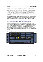
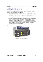
7-1 depicts the layout of the basic XDM-100 shelf.
I/O modules
MXC-100
cards
FCU
Aggregate
modules
ECU card
CRT
MON
AC
T
FA
IL
MAJ
MIN
WAR
US B
AL AR MS
D EB UG
F- CHA NN EL
T3_1/ T4_ 1
T3 _2/T 4_2
M N G
M N G
M AI N
PR O T
M OD UL E
CH AN NE L
ECU
S TM 1
M ON
LAS ER
A CT IVE
L ED
TES T
A CO
A C
FL
T R
OU T
IN
ON
M O N
C LK
MO N
S A M 16 _ 1
M AI N
AC T
FAI L
TM U
NV M
MXC-100
POWER IN A
POWER IN B
A DB
A C
F L
T R
O UT
I N
ON
MO N
CLK
M ON
S A M 16 _ 1
M A IN
A CT
FAI L
T MU
NV M
MXC-100
POWER IN A
POWER IN B
A DB
AC
FL
TR
S IM4 _2
O UT 1
IN 1 OU T2
I N2
ON
O N
M O N
MO N
M ON
AC
FL
TR
S IM 4 _2
O UT 1
IN 1 OU T2
I N2
ON
O N
M O N
MO N
M ON
A C
FL
TR
P IM3 45 _ 3
IN 1
I N2
I N3
OU T1
O UT 2
OU T3
MO N
MO N
MO N
M O N
A C
FL
TR
P IM3 45 _ 3
IN 1
I N2
I N3
OU T1
O UT 2
OU T3
MO N
MO N
MO N
M O N
A C
FL
T R
M ON
IN 1 -21
OU T 1-2 1
MO N
A C
FL
T R
P IM 2_ 21
M ON
IN 1 -21
OU T 1-2 1
MO N
A C
F L
T R
P IM 2_ 21
M O N
OU T 1- 21
I N 1-2 1
MO N
A C
FL
T R
P IM 2_ 21
P IM2 _ 21
M ON
IN 1 -21
OU T 1-2 1
MO N
N VM
N VM
A C
FL
TR
OU T1
IN 1 OU T2
I N2
O UT 3
I N3 O U T4
IN 4
ON
MO N
ON
M O N
O N
M ON
O N
MO N
S A M 1_ 4 /0
A C
F L
TR
O UT 1
IN 1 OU T2
IN 2
O UT3
I N3 O UT 4
IN 4
ON
M O N
O N
M ON
O N
M ON
O N
MO N
S A M 1_ 4 /0
- +
- +
- +
- +
XDM -100
AC T IV E
FA IL
FCU
R
LAS ER KLA SSE
1
CLA
SS 1
L
ASER PRODUCT
HAZ
ARD CL
ASS 1M
LA
SER R
ADI A
TI ON
WHEN OPEN AVOID
EXP
O S
URE TO T
HE B
EAM
RES ET
RE SET
WAR NI NG !!!
R E M OV E S A M /OS C
M OD U L E S
B E F OR E C A R D
E X T RA C T ION
WAR NIN G !!!
R E MO V E S A M /OS C
M ODU L E S
B E F ORE C A R D
E X T RA C T IO N
Figure
7-1: Basic XDM-100 shelf layout
The basic XDM-100 cage contains slots for I/O interface modules, and dedicated
slots for the MXC cards and the ECU. The cage’s design and mechanical practice
conform to international mechanical standards and specifications.
The modules and cards are distributed as follows:
♦
Eight (8) slots, I1 to I8, optimally allocated for I/O interface modules.
♦
Two (2) slots, A and B respectively, allocated for the MXC cards (main and
protection). Each MXC card has two slots (A1 and A2 and B1 and B2) to
accommodate SDH/SONET aggregate modules.
♦
One (1) slot allocated for the ECU card.
The ECU is located beneath the MXC cards. Its front panel features several interface
connectors for management, external timing, alarms, orderwire, and overhead
(future release). It also includes alarm severity colored LED indicators and selectors
plus a display for selecting specific modules and ports for monitoring purposes.
Содержание XDM-100
Страница 1: ...XDM 100 Miniature MSPP for Metro Access and Cellular Networks General Description ...
Страница 3: ...XDM 100 ...
Страница 8: ...Contents XDM 100 iv ECI Telecom Ltd Proprietary 417006 2005 013 A02 ...
Страница 10: ...Contents XDM 100 vi ECI Telecom Ltd Proprietary 417006 2005 013 A02 ...
Страница 12: ...Contents XDM 100 viii ECI Telecom Ltd Proprietary 417006 2005 013 A02 ...
Страница 16: ...Introduction XDM 100 1 4 ECI Telecom Ltd Proprietary 417006 2005 013 A02 ...
Страница 22: ...Applications XDM 100 2 6 ECI Telecom Ltd Proprietary 417006 2005 013 A02 ...
Страница 30: ...System Characteristics XDM 100 3 8 ECI Telecom Ltd Proprietary 417006 2005 013 A02 ...
Страница 37: ...XDM 100 System Design 417006 2005 013 A02 ECI Telecom Ltd Proprietary 4 7 Figure 4 3 General block diagram ...
Страница 44: ...System Design XDM 100 4 14 ECI Telecom Ltd Proprietary 417006 2005 013 A02 ...
Страница 82: ...XDM 100H XDM 100 8 8 ECI Telecom Ltd Proprietary 417006 2005 013 A02 ...
Страница 94: ...Glossary XDM 100 B 6 ECI Telecom Ltd Proprietary 417006 2005 013 A02 ...
Страница 98: ...Index XDM 100 I 4 ECI Telecom Ltd Proprietary 417006 2005 013 A02 ...


