Echelon LonWorks MPR-50 Скачать руководство пользователя страница 49


17.


The log area of the MPR-50 Buffer Management utility main window shows 

“Buffer configuration complete” when the buffers have been successfully 

modified. 


18.


Click the 

Routers Found

 Button to clear the list of registered routers. 


19.


Press each MPR router service pin.  The buffers sizes are displayed in the Log 

Box. 


20.


When the buffer configuration is complete, click 

Exit

 to close the MPR-50 Buffer 

Management utility. 


Changing the Utility’s Buffer Sizes  

The utility uses a text file that presents up to four separate “Buffer Configurations”. 

This is a comma-separated value (CSV) file that contains an informational header 

plus various buffer configuration fields. The file name is “buffconfig.csv”, and you can 

edit it with a text editor or a spreadsheet application (such as Microsoft Excel).  This 

file must exist in the same folder as the utility’s executable file.  Also provided is an 

alternative CSV file that shows how to support 255 byte buffers (see the “Alternate 

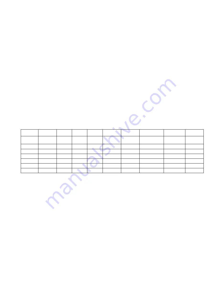
CSV” sub-directory).  Table 1 shows an example of the file layout. 


Table 1. 

Buffer Configuration File


# This is a 
comment. 


NodeID Name 

NetBuff 
Size 

AppBuff 
Size 

NetBuffIn
Count 

NetBuffOut 
Count 

NetBuffOut 
PriCount 

AppBuffInCount AppBuffOut 

Count 

AppBuffOut
PriCount 

EXTFT10 66 

Bytes  66 

42 

INTDIFF 66 

Bytes  66 

42 

11 

EXTTP12 66 

Bytes  66 

42 

127 

191 

63 

EXTFT10 114 

Bytes  114 

42 

INTDIFF 114 

Bytes 114 

42 

EXTTP12 114 

Bytes  114 

42 

47 

127 

31 


The “NodeID” field must contain one of the following values: 


EXTFT10 


INTDIFF 


EXTTP12  


The “Name” field is used to create one of the four unique buffer configurations that 

appear in the “Buffer Configurations” area of the utility.  


The rest of the fields refer to standard Neuron buffer configurations values. The 

order of the rows in the file are only important in that the first three entries are used 

to set the default values.  However, the order of the columns are important because 

they are always assigned in the order that matches the descriptors listed in the table 

(the program doesn’t use these descriptors; they are purely informative for the CSV 

file).  


For each unique configuration “Name” value, there should be 3 entries, one for each 

NodeID.  The utility checks all values against the acceptable buffer configuration 

MPR-50 Multi-Port Router User's Guide 

 41 

Содержание LonWorks MPR-50

Страница 1: ...MPR 50 Multi Port Router User s Guide 078 0308 01B...

Страница 2: ...tured by vendors other than Echelon and referenced in this document have been described for illustrative purposes only and may not have been tested by Echelon It is the responsibility of the customer...

Страница 3: ...ence will not occur in a particular installation If this equipment does cause harmful interference to radio or television reception which can be determined by turning the equipment off and on the user...

Страница 4: ......

Страница 5: ...Preface This document describes how to install and use Echelon s MPR 50 Multi Port Router and is written for system designers and installers MPR 50 Multi Port Router User s Guide i...

Страница 6: ...overview Chapter 2 describes the router hardware and how to connect it to a network Software content is described too Chapter 3 describes how to install the router on a network Chapter 4 introduces th...

Страница 7: ...Connecting to the Network 11 Installing the MPR 50 on a Network 12 Repeater Mode 12 Commissioning with Network Tools other than the LonMaker Tool 12 Commissioning with the LonMaker Integration Tool 1...

Страница 8: ...ent Utility 35 Buffer Management Utility 36 Installing and Running the MPR Buffer Management Utility 37 Using the MPR Program 37 Checking the Current Buffer Sizes 37 Using Buffer Configure 37 Using Bu...

Страница 9: ...1 Overview This chapter introduces Echelon s MPR 50 Multi Port Router MPR 50 Multi Port Router User s Guide 1...

Страница 10: ...r supply a LONMARK certified Monitor that displays status locally on LEDs as well as provides status and a time stamped alarm log that is accessible via the network In addition the router includes an...

Страница 11: ...50 Multi Port Router hardware including enclosure construction mounting instructions explanation of indicators and connectors and wiring guidelines In addition the Multi Port Router CD contents and i...

Страница 12: ...ecting The MPR 50 Multi Port Router enclosure is designed for mounting on a DIN rail or wall panel A spring loaded DIN rail lock securely grabs the DIN rail onto which the enclosure is mounted Tabs in...

Страница 13: ...50 Multi Port Router Enclosure back view Key Hole Slots for Mounting DIN Rail Lock Use the following steps to mount the router 1 Insert two 6 32 flat head screws into the surface upon which the MPR 50...

Страница 14: ...f the enclosure The screw terminals accept 0 34 4 0 mm2 22 12AWG gauge wire The optimum tightening torque for the screw terminals is 0 75mm 6 lbs in maximum The ideal flathead screwdriver tip width fo...

Страница 15: ...1 through Router 5 to the desired channels Router 1 is for the TP XF 1250 channel while Routers 2 5 are for the TP FT 10 channels TP XF 1250 and TP FT 10 channel wiring is polarity insensitive and th...

Страница 16: ...lashing Repeater mode Routers 1 5 will repeat all valid traffic This mode is useful for plug n play use without network management tools Slow flashing is defined as on for one second off for one secon...

Страница 17: ...ter Status LED does not indicate the router state the router will still be routing if it was previously configured to do so If the Monitor LED is not yellow on then the router is disabled or offline a...

Страница 18: ...aces such as the PCC 10 PC Card Network Interface and the U10 USB Network Interface Software The MPR 50 Multi Port Router CD includes the following content ReadMe Quick Start Guide User s Guide Softwa...

Страница 19: ...3 Connecting to the Network This chapter demonstrates how to install the MPR 50 Multi Port Router on a network MPR 50 Multi Port Router User s Guide 11...

Страница 20: ...ot just on the noisy channel but on the entire network Networks that have low traffic density and protocol routing is not required When in the repeater mode the MPR 50 does not segregate traffic and m...

Страница 21: ...open it from File Stencils 2 Drag a MPR 50 master shape from the Multi Port Router Shapes stencil onto the drawing 3 The Channel Definition dialog appears Most users will want to click OK repeatedly...

Страница 22: ...t menu Note You cannot move LonMaker shapes using Visio s cut and paste commands Commissioning an MPR 50 Router 1 Right click the shape of the router that you have connectivity to from your LonMaker t...

Страница 23: ...directly enter its Neuron ID 5 Click Finish The Press Service Pin window appears 6 Press the service pin of the router The LonMaker tool commissions the router 7 Click the Monitor shape and hold down...

Страница 24: ...f CP Values and Device Specific CPs options as appropriate See the LonMaker User s Guide for an explanation of the effects of the various options 9 Click Next The Commission Device Wizard appears 16 C...

Страница 25: ...elect the initial states of the routers being commissioned Most end users will want to choose online 11 Click Next The Device Identification Method window appears MPR 50 Multi Port Router User s Guide...

Страница 26: ...r and the routers being commissioned in the order presented in the window Buffers The default buffer sizes for the MPR 50 Multi Port Router support LONMARK standard message sizes The sizes and counts...

Страница 27: ...ternal Side Routers 2 5 Type Size Count app_buf_out_size 42 app_buf_in_size 42 app_buf_out_count 2 app_buf_in_count 2 app_buf_out_priority_count 1 net_buf_out_size 114 net_buf_in_size 114 net_but_out_...

Страница 28: ...20 MPR 50 Monitor...

Страница 29: ...4 MPR 50 Monitor This chapter describes the interfaces and functionality of the MPR 50 s Monitor MPR 50 Multi Port Router User s Guide 21...

Страница 30: ...er 1 1250 and Channel 1 1250 1 Router 2 TP FT 10 Router 2 FT and Channel 2 FT 2 Router 3 TP FT 10 Router 3 FT and Channel 3 FT 3 Router 4 TP FT 10 Router 4 FT and Channel 4 FT 4 Router 5 TP FT 10 Rout...

Страница 31: ...nds this will set the MPR 50 to the factory default state or commission Routers 1 5 with a network management tool in this case it is not necessary to first take the MPR 50 out of repeater mode Two co...

Страница 32: ...se this variable nvoFileDirectory File Directory SNVT_address Contains the memory address for the file directory containing descriptors for configuration files Used by network management tools to read...

Страница 33: ...however the network tool should send valid values The default state is OFF The Status LED behavior is described in Chapter 2 MPR 50 Multi Port Router Hardware and Software The error log is described i...

Страница 34: ...rror Log Certain network variables that are part of the Channel Monitor functional blocks are alarmed and the Monitor maintains an error log of any alarm conditions The log is circular the entries are...

Страница 35: ...a network management tool is reading it In order to ensure that reads are consistent read the error log only after all of the Channel Monitor functional blocks are temporarily disabled Channel Monitor...

Страница 36: ...er of messages in any interval since last reset or clearance of statistics nvoAvgPackets Average Packets SNVT_count_32 Average number of packets per interval since last reset or clearance of statistic...

Страница 37: ...The default is 0 for all channels and should not be changed Alarms The Monitor implements LONMARK alarms for several network variables in the Channel Monitor functional blocks The alarmed network vari...

Страница 38: ...alue The nvoIvalCrcErr and nvoIvalMissed variables have a high alarm limit SCPThighLimit1 and do not have a low alarm limit A hysteresis value SCPThystHigh1 is used to prevent oscillation of the alarm...

Страница 39: ...ice without maintenance In the unlikely event that a problem arises this chapter describes how to diagnose and correct the problem If the problem cannot be readily corrected please contact Echelon Sup...

Страница 40: ...n commissioned properly by the network tool or is in repeater mode Verify that the network wiring is functional by pressing the Service button on any intervening routers and on the router inside the M...

Страница 41: ...f the MPR 50s in the network is defined within the network tool as a separate channel The MPR 50 does not pass messages larger than 114 bytes The MPR 50 can support messages up to 256 bytes Configure...

Страница 42: ...34 Appendix A Buffer Management Utility...

Страница 43: ...Appendix A Buffer Management Utility This appendix explains how to use the buffer management utility for the MPR 50 Multi Port Router MPR 50 Multi Port Router User s Guide 35...

Страница 44: ...ded see Changing the Utility s Buffer Sizes Figure 1 MPR 50 Buffer Management Utility Main Window Button Action Open Close Opens Closes a Network Interface Buffer Configure Changes the Buffer size to...

Страница 45: ...close the Network Interface Checking the Current Buffer Sizes To check the MPR 50 buffer sizes 1 Make sure the Buffer Recover Mode button is off i e grey background 2 Click the Routers Found Button t...

Страница 46: ...figuration mode 8 Press the Service Pin button on all of the MPR 50 s routers As you press each of the Service Pins notice that the number displayed on the Routers Found button of the MPR 50 Buffer Ma...

Страница 47: ...e utility uses the same Neuron ID to send a buffer configuration message to the far router node using the un ack d service The router is reset as a result 4 After another small delay the utility reads...

Страница 48: ...lly modified 11 Repeat steps 9 and 10 until you have fixed the buffers for all five routers 12 If you want to use the default buffer size of 114 bytes proceed to step 18 Otherwise proceed to the next...

Страница 49: ...n File This is a comment NodeID Name NetBuff Size AppBuff Size NetBuffIn Count NetBuffOut Count NetBuffOut PriCount AppBuffInCount AppBuffOut Count AppBuffOut PriCount EXTFT10 66 Bytes 66 42 7 7 2 2 2...

Страница 50: ...guration that exceeds the available RAM for the particular NodeID type the utility displays an error and the configuration will not proceed The utility communicates with the router nodes using Neuron...

Страница 51: ...www echelon com...

Отзывы: