Page 12 of 15
Com Port setup needs to be run every time the Configuration Tool is opened.
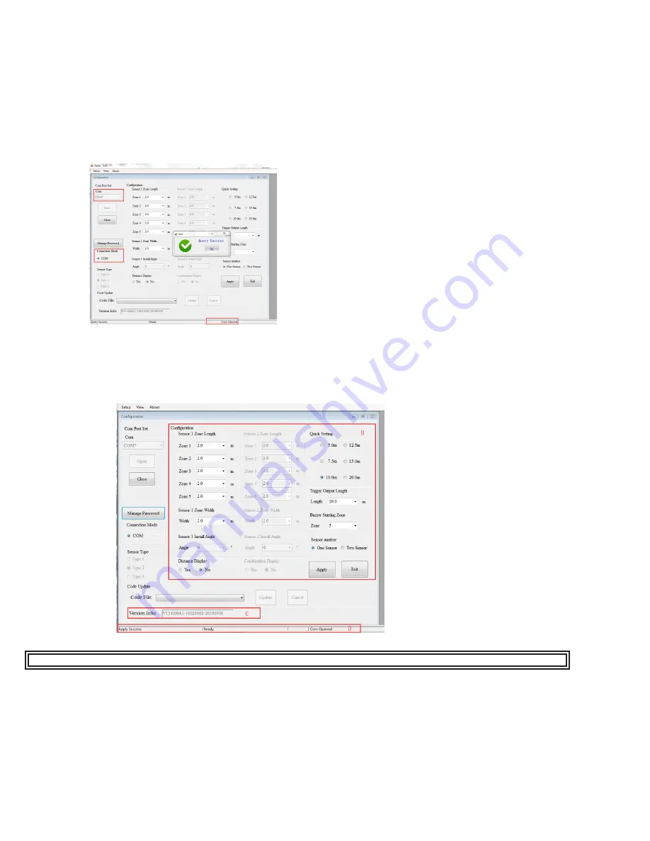
NOTE: “Query Success OK” will show once the sensor(s) has been detected.
8.3.3 Reading Configuration from the Control Box:
By clicking the “Open” button via COM, the Configuration Tool will send a query instruction to the Control Box and read
configuration data from the Control Box. Once the configuration has been read successfully, the latest configuration data is
displayed in part B, the firmware version information is displayed in part C and connection status is displayed in part D.
WARNING! Connection between the control box and the PC must be maintained while using the configuration tool.
8.3.4 Reading Configuration from the Control Box:
The part B is a configuration group box. This is used to configure “Sensor Zone Length Configuration”, “Quick Setting”, “Sensor
Zone Width”, “Combination Display”, “Trigger Output Length” and “Buzzer Starting Zone”.
8.3.4.1 Sensor Zone Length :
The detection area length can be set in two ways;
1: Setting each zone individually via the “Sensor 1 Detection Zone Length”. “Sensor 1 Detection Zone Length” can be set
when you choose sensor number as two sensors.
2: Setting each zone quickly via the “Quick Setting”.
Figure 22
Figure 21
8.3.2.1 Connecting via USB to UART Cable :
Select the COM Mode. To check the COM port number you are using for the connected Control Box on the PC you will need
to open Windows “Device Manager”.
In the Device Manager window click “Ports (COM & LPT)” and check “Silicon Labs CP210x USB to UART Bridge (COM##)”.
The “##” represents the number of the port through which the display is currently connected to the PC.
The COM port identified before should be used by selecting it from the drop down list and then click “Open”. When the
connection is successful, “Com Closed” will change into “Com Opened” at the bottom status bar.
8.3.2 Connecting Control Box:


