

Chengdu Ebyte Electronic Technology Co., Ltd
Copyright ©2012–2019
,
Chengdu Ebyte Electronic Technology Co.,Ltd.
5
9
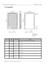
LCD-SEG1
7
Input/output
MCU GPIO
10
I2C-SDA
Input/output
I2C-SDA pin
11
I2C-SCL
Input/output
I2C-SCL pin
12
ADC-IN0
Input
ADC input pin
13
ADC-IN1
Input
ADC input pin
14
GPIO2
Input/output
MCU GPIO
15
GPIO3
Input/output
MCU GPIO
16
GPIO4
Input/output
MCU GPIO
17
ADC_IN2
Input
ADC input pin
18
GND
Ground wire, connected to the power reference ground
19
ANT
output
Antenna interface, stamp hole (50 ohm characteristic impedance)
20
GND
Ground wire, connected to the power reference ground
21
GND
Ground wire, connected to the power reference ground
22
GND
Ground wire, connected to the power reference ground
23
GND
Ground wire, connected to the power reference ground
24
SPI-NSS
Input
SPI select pin, can select external SPI
25
SPI-SCK
Input
SPI-SCK pin, can be used as external SPI
26
SPI_MISO
output
SPI_MISO pin, can be used as external SPI
27
SPI_MOSI
Input
SPI MOSI pin, can be used as external SPI
28
LCD-SEG1
MCU GPIO
29
LCD-SEG2
Input/output
MCU GPIO
30
SWIM
Input/output
Program burning pin
31
NRST
Input
External reset pin
32
LCD-COM
0
Input/output
MCU GPIO
33
LCD-COM
1
Input/output
MCU GPIO
34
LCD-COM
2
Input/output
MCU GPIO
35
VREFP
Input
ADC reference voltage input
36
UART1-RX
Input
UART1-RX pin
37
UART1-TX
output
UART1-TX pin
38
VLCD
Input
VLCD pin
39
LCD-SEG0
Input/output
MCU GPIO
40
GND
Ground wire, connected to the power reference ground
41
LCD-SEG3
Input/output
MCU GPIO
42
LCD-COM
3
Input/output
MCU GPIO
43
LCD-SEG4
Input/output
MCU GPIO
44
LCD-SEG5
Input/output
MCU GPIO
45
UART0-RX
Input
UART0-RX pin