background image


Chapter 2 

2.1. Peripherals Installation 

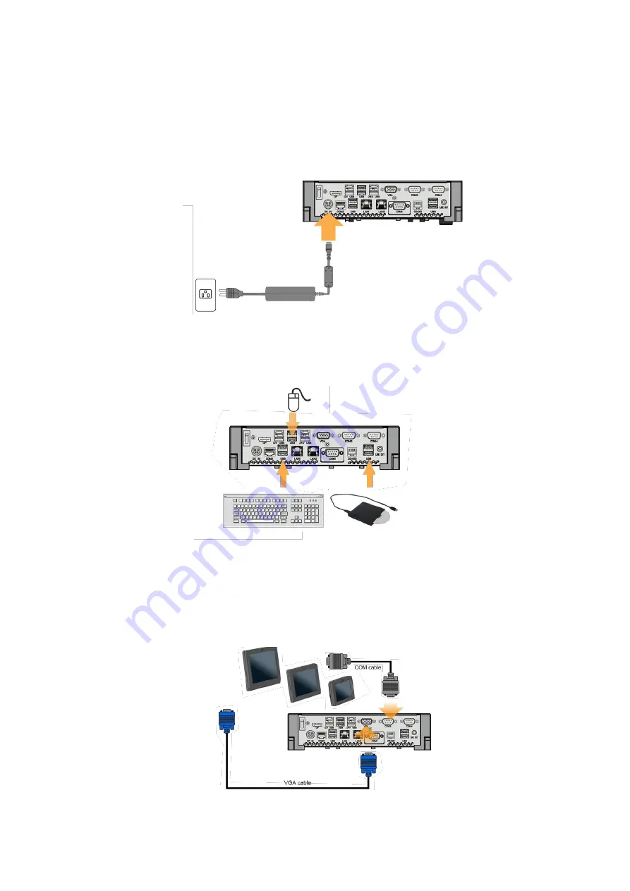
Power Adapter   

Connect the output jack of the adapter to the 

DC in

 jack on the back panel of the 

device. 

CAUTION: Connect the power jack of the adapter to the device first and then 

connect the power cord to the AC outlet. 


USB Mouse, USB Keyboard and USB ODD 

Connect your USB Mouse, USB Keyboard and USB ODD to 

USB

 ports on the 

back panel of the device. 


VGA LCD Touchscreen Monitor   

1.  Connect one end of the Serial Port Cable to the 

COM 

male port on the back 

panel of the device, another end to the COM port of your LCD panel. 

2.  Connect one end of the VGA cable to the 

VGA

 female port on the back panel 

of the device, another end to the VGA port of your LCD panel. 


Содержание Boxster 5

Страница 1: ...User s Manual Boxster 5...

Страница 2: ...and can radiate radio frequency energy and if not installed and used in accordance with the instructions may cause harmful interference to radio communications However there is no guarantee that inter...

Страница 3: ...rk for the return and recycling of used appliances as applicable throughout the European Union This label is applied to various products to indicate that the product is not to be thrown away but rathe...

Страница 4: ...ii 1 Hardware Setup 1 1 1 Unpacking the Box 1 2 Quick Tour 2 2 1 Peripherals Installation 3 Power Adapter 3 USB Mouse USB Keyboard and USB ODD 3 VGA LCD Touchscreen Monitor 3 Cash Drawer 4 2 2 Turn on...

Страница 5: ...Chapter 1 1 1 1 Hardware Setup 1 1 Unpacking the Box The Device X 1 Power Adaptor X 1 Power Cord X 1 Driver and Utility CD X 1 RJ50 to DB9 COM port adapter cable X 1 Wall Mount Kit...

Страница 6: ...ill glow green when power is on The HDD indicator will blink green when the HDD is accessed The LAN indicator will blink green when transferring data though the LAN 2 2 Rear View Note For details of I...

Страница 7: ...he AC outlet USB Mouse USB Keyboard and USB ODD Connect your USB Mouse USB Keyboard and USB ODD to USB ports on the back panel of the device VGA LCD Touchscreen Monitor 1 Connect one end of the Serial...

Страница 8: ...o your internet device Cash Drawer Connect one end of RJ 12 cable to the Cash Drawer port on the back panel of the device another end to your cash drawer 2 2 Turn on the Device 1 Make sure all periphe...

Страница 9: ...as followings 3 1 Power Connector PIN Description PIN Description 1 GROUND 3 19V 2 GROUND 4 19V 3 2 Serial Port COM Port 1 2 3 PIN Description PIN Description 1 DCD 6 DSR 2 RXD 7 RTS 3 TXD 8 CTS 4 DTR...

Страница 10: ...6 2 D_OUT0 5 D_OUT1 3 D_IN 6 GND Cash Drawer Control Status Address Value Open 280H Bit 4 0 Close 280H Bit 4 1 Read Status 281H Bit 0 0 1...

Страница 11: ...Chapter 5 7 4 5 Specification 4 1 The Device...

Страница 12: ...V 12V Selectable by BIOS COM 1 RS 232 422 485 DB 9 COM 2 RS 232 RJ50 10 pins w COM cable COM 3 4 RS 232 DB 9 USB 2 x USB 3 0 6 x USB 2 0 Powered USB 1 x 12V powered USB 2A 1 x 24V powered USB 2A LAN 2...

Страница 13: ...Chapter 5 9 Dimension 234Wx188 2Dx59 8H mm Weight 1 5 kg Operating Temperature 0 C 50 C Storage Temperature 20 C 60 C Humidity 5 95 RH non condensing ESD Contact discharge 6KV Air discharge 15KV...

Отзывы: