background image

Operating instructions

R2E225-RA92-09

Translation of the original operating instructions

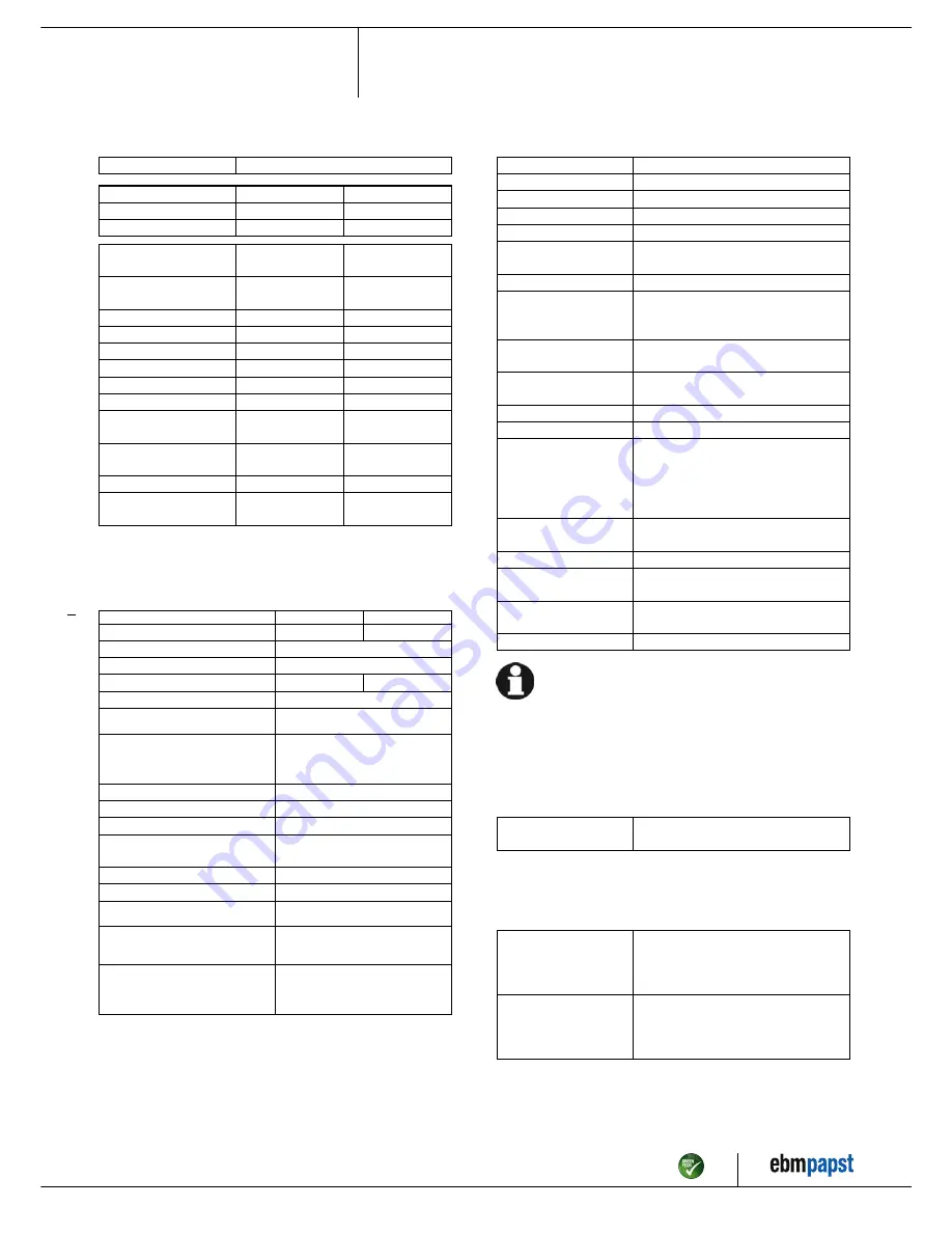
3.2 Nominal data

Motor

M2E068-DF

Phase

1~

1~

Nominal voltage / VAC

230

230

Frequency / Hz

50

60

Method of obtaining
data

ml

ml

Valid for approval/
standard

CE

CE

Speed / min

-1

2500

2600

Power consumption / W

155

210

Current draw / A

0.68

0.92

Capacitor / µF

3.5

3.5

Capacitor voltage / VDB

450

450

Min. back pressure / Pa

0

0

Min. ambient
temperature / °C

-25

-25

Max. ambient
temperature / °C

70

65

Starting current / A

1.25

1.2

Max. safe operating
speed / min

-1

3600
@ 80 °C

3600
@ 80 °C

ml = Max. load · me = Max. efficiency · fa = Free air

cs = Customer specification · ce = Customer equipment

Subject to change

3.3 Data according to ErP Directive

Actual

Req. 2015

01 Overall efficiency η

es

/ %

42.5

42.5

02 Measurement category

A

03 Efficiency category

Static

04 Efficiency grade N

62

62

05 Variable speed drive

No

06 Year of manufacture

The year of manufacture is specified on the
product's rating label.

07 Manufacturer

ebm-papst Mulfingen GmbH & Co. KG
Amtsgericht (court of registration) Stuttgart ·
HRA 590344
D-74673 Mulfingen

08 Type

R2E225-RA92-09

09 Power consumption P

e

/ kW

0.14

09 Air flow q

v

/ m³/h

705

09 Pressure increase total p

sf

/

Pa

320

10 Speed n / min

-1

2560

11 Specific ratio

*

1.00

12 Recycling/disposal

Information on recycling and disposal is
provided in the operating instructions.

13 Maintenance

Information on installation, operation and
maintenance is provided in the operating
instructions.

14 Additional components

Components used to calculate the energy
efficiency that are not apparent from the
measurement category are detailed in the
CE declaration.

*

Specific ratio = 1 + p

fs

/ 100 000 Pa

Data obtained at optimum efficiency level. The ErP data is determined using a motor-impeller

combination in a standardized measurement setup.

3.4 Technical description

Fan size

225 mm

Rotor surface

Painted black

Impeller material

PA6 plastic, glass-fiber reinforced

Number of blades

7

Direction of rotation

Clockwise, viewed toward rotor

Degree of protection

IP44; installation- and position-dependent
as per EN 60034-5

Insulation class

"F"

Moisture (F) /
Environmental (H)
protection class

H0+

Installation position

Shaft horizontal or rotor on bottom; rotor
on top on request

Condensation
drainage holes

On rotor side

Mode

S1

Motor bearing

Ball bearing

Touch current
according to IEC
60990 (measuring
circuit Fig. 4, TN
system)

< 0.75 mA

Motor protection

Thermal overload protector (TOP)
internally connected

with cable

Variable

Protection class

I (with customer connection of protective
earth)

Conformity with
standards

EN 60335-1; CE

Approval

EAC; CCC

With regard to cyclic speed loads, note that the rotating parts of
the device are designed for a maximum of one million load
cycles. If you have special questions, consult ebm-papst for
support.

3.5 Mounting data

For screw clearance, see Chapter 3.1 Product drawing

;

Secure the screws against unintentional loosening (e.g. use self-
locking screws).

Strength class of
screws

8.8

Any further mounting data required can be taken from the product drawing.

3.6 Transport and storage conditions

;

Use the device in accordance with its degree of protection.

Max. permitted
ambient temp. for
motor (transport/
storage)

+ 80 °C

Min. permitted
ambient temp. for
motor (transport/
storage)

- 40 °C

Item no. 10989-5-9970 · ENU · Change 89188 · Approved 2016-04-18 · Page 5 / 9

ebm-papst Mulfingen GmbH & Co. KG · Bachmühle 2 · D-74673 Mulfingen · Phone +49 (0) 7938 81-0 · Fax +49 (0) 7938 81-110 · [email protected] · www.ebmpapst.com

Содержание R2E225-RA92-09

Страница 1: ...ed unpacked installed operated maintained and otherwise used by suitably qualified trained and authorized technical staff Only authorized specialists are permitted to install the device to carry out a test run and to perform work on the electrical installation 1 3 Basic safety rules 1 1 3 Basic safety rules The safety hazards associated with the device must be assessed again following installation...

Страница 2: ... contact Before working on the system machine wait until all parts have come to a standstill WARNING Rotating device Long hair and dangling items of clothing jewelry and the like can become entangled and be pulled into the device Injuries can result Do not wear any loose fitting or dangling clothing or jewelry while working on rotating parts Protect long hair with a cap 1 7 Emissions WARNING Depen...

Страница 3: ...tive devices Following the operating instructions Improper use In particular operating the device in the following ways is prohibited and could be hazardous Operating the device in an unbalanced state e g due to dirt deposits or ice formation Conveying air that contains abrasive particles Conveying highly corrosive air e g salt spray Exception devices designed for salt spray and correspondingly pr...

Страница 4: ...e silicone 4G 0 5 mm 4x crimped splices 2 Accessory part inlet ring 96358 2 4013 not included in scope of delivery 3 Max clearance for screw 5 mm Item no 10989 5 9970 ENU Change 89188 Approved 2016 04 18 Page 4 9 ebm papst Mulfingen GmbH Co KG Bachmühle 2 D 74673 Mulfingen Phone 49 0 7938 81 0 Fax 49 0 7938 81 110 info1 de ebmpapst com www ebmpapst com ...

Страница 5: ... pfs 100 000 Pa Data obtained at optimum efficiency level The ErP data is determined using a motor impeller combination in a standardized measurement setup 3 4 Technical description Fan size 225 mm Rotor surface Painted black Impeller material PA6 plastic glass fiber reinforced Number of blades 7 Direction of rotation Clockwise viewed toward rotor Degree of protection IP44 installation and positio...

Страница 6: ...ly use cables designed for the current level indicated on the nameplate For determining the cross section note the sizing criteria according to EN 61800 5 1 The protective earth must have a cross section equal to or greater than that of the phase conductor We recommend the use of 105 C cables Ensure that the minimum cable cross section is at least AWG 26 0 13 mm Ground conductor contact resistance...

Страница 7: ...ructions 4 4 Connection diagram U1 blue Z brown U2 black PE green yellow Item no 10989 5 9970 ENU Change 89188 Approved 2016 04 18 Page 7 9 ebm papst Mulfingen GmbH Co KG Bachmühle 2 D 74673 Mulfingen Phone 49 0 7938 81 0 Fax 49 0 7938 81 110 info1 de ebmpapst com www ebmpapst com ...

Страница 8: ...ce CAUTION Electric charge on capacitor after device is switched off Electric shock risk of injury Discharge the capacitors before working on the device CAUTION The motor restarts automatically when operating voltage is applied e g after a power failure Risk of injury Keep out of the device s danger zone When working on the device switch off the line voltage and ensure that it cannot be switched b...

Страница 9: ...untry specific legal regulations with regard to the disposal of products or waste occurring in the various phases of the life cycle The corresponding disposal standards are also to be heeded 5 3 2 Disassembly Disassembly of the product must be performed or supervised by qualified personnel with the appropriate technical knowledge The product is to be disassembled into suitable components for dispo...

Отзывы: