background image

Operating instructions

K3G630-AP01-90

`

II 2G Ex db eb ib IIB T3 Gb

IBExU14ATEX1122 X /05

`

Translation of the original operating instructions

54007-4-8670

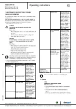
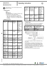
5.5 Connection diagram

Drawing preliminary!

Shaded => terminals not used

No.

Conn.

Designation

Function/assignment

1

PE

Ground connection, PE connection

1

L1

Supply connection, power supply 3-phase 380-440 VAC, 50/60 Hz

1

L2

Supply connection, power supply 3-phase 380-440 VAC, 50/60 Hz

1

L3

Supply connection, power supply 3-phase 380-440 VAC, 50/60 Hz

1

HZ

not used (optional: internal heating element)

2

RSA

Bus connection RS485, RSA, MODBUS RTU; double terminal point (SELV)

2

RSB

Bus connection RS485, RSB, MODBUS RTU; double terminal point (SELV)

2

GND

Reference ground for control interface (SELV)

2

Ain1 U

Analog input 1, set value: 0-10 V, Ri = 100 kΩ, adjustable curve, only usable as alternative to input Ain1 I;
SELV

2

+10 V

Fixed voltage output 10 VDC, +10 V ±3%, max. 10 mA, short-circuit-proof power supply for external devices
(e.g. pot); SELV

2

Ain1 I

Analog input 1, set value: 4-20 mA, Ri = 100 Ω, adjustable curve, only usable as alternative to input Ain1 U;
SELV

2

Din 1

Digital input 1: enable electronics,
enable: pin open or applied voltage 5-50 VDC
disable: bridge to GND or applied voltage < 1 VDC
reset function: triggers software reset after a level change to < 1 VDC; SELV

2

Aout

Analog output 0-10 VDC, max. 5 mA, output of current motor modulation level / motor speed
adjustable curve; SELV

2

Din 2

Digital input 2: Switching parameter sets 1/2, according to EEPROM setting, the valid or used parameter set
can be selected via bus or via digital input DIN2.
Parameter set 1: pin open or applied voltage 5-50 VDC
Parameter set 2: bridge to GND or applied voltage < 1 VDC; SELV

2

Din 3

Digital input 3: Direction of action of integrated controller, according to EEPROM setting, the direction of action
of the integrated controller can be selected as normal/inverse via bus or digital input
Normal: Pin open or applied voltage 5-50 VDC
Inverse: Bridge to GND or applied voltage < 1 VDC; SELV

2

Ain2 U

Analog input 2, measured value: 0-10 V, Ri = 100 kΩ, adjustable curve, only usable as alternative to input
Ain2 I; SELV

2

+20 V

Fixed voltage output 20 VDC, +20 V +25/-10%, max. 50 mA, short-circuit-proof power supply for external
devices (e.g. sensors); SELV
or: +24 VDC input for parameter setting via MODBUS without line voltage

2

Ain2 I

Analog input 2, measured value: 4-20 mA, Ri = 100 Ω, adjustable curve, only usable as alternative to input
Ain2 U; SELV

2

NO

Status relay, floating status contact; make for failure

2

COM

Status relay, floating status contact, common connection, contact rating 250 VAC / max. 2 A (AC1) / min. 10
mA

2

NC

Status relay; floating status contact, break for failure

Item no. 54007-5-9970 · ENU · Change 272968 · Approved 2022-11-23 · Page 15 / 18

ebm-papst Mulfingen GmbH & Co. KG · Bachmühle 2 · D-74673 Mulfingen · Phone +49 (0) 7938 81-0 · Fax +49 (0) 7938 81-110 · [email protected] · www.ebmpapst.com

Содержание K3G630-AP01-90

Страница 1: ...g instructions are available in other languages on our website www ebmpapst com 2 2 SAFETY REGULATIONS AND INFORMATION 2 2 1 Hazard levels for warnings 2 2 2 Staff qualifications 2 2 3 Basic safety ru...

Страница 2: ...h the operating instructions Malfunctions and defects that affect safety must always be corrected immediately No modifications additions or conversions are to be made to the device for example changes...

Страница 3: ...d its attachment must always be evaluated in connection with the overall safety concept of the system as a whole 2 8 Emissions WARNING Depending on the installation and operating conditions the sound...

Страница 4: ...and 1050 mbar Using the device within the permitted ambient temperature range see Chapter 4 2 Nominal data and Chapter 4 5 Transport and storage conditions The device is to be protected against exposu...

Страница 5: ...ompliance include personal injury and property damage due to shaft breakage fatigue failure reduced bearing service life or explosions caused by elevated surface temperatures or sparking Item no 54007...

Страница 6: ...value depending on cable 6 Terminal box fastening screws tightening torque 3 5 0 5 Nm 7 Ground connection point M8 functional ground for electrostatic discharge no protective earth do not unfasten th...

Страница 7: ...e product drawing The other bolts must not be loosened Used screws and nuts must be disposed of Use the fastening components available from ebm papst for assembly If the housing is painted the contact...

Страница 8: ...tor on top not permitted Condensation drainage holes On rotor side Mode S1 Motor bearing Ball bearing Technical features Output 10 VDC max 10 mA Output 20 VDC max 50 mA Output for slave 0 10 V Operati...

Страница 9: ...of safety 4 8 The nameplate Fig 1 Specifications on the nameplate Serial number Designation Explanation YY Year Year e g 11 for production in 2011 WW Week Week calendar week in year of production Six...

Страница 10: ...d to force or excessive vibration from sections of the installation If the fan is connected to air ducts the connection should be isolated from vibration e g using compensators or similar elements Ens...

Страница 11: ...ambient temperature Do not subject the cables to impermissible strain Establish a safe protective earth connection Ensure that the degree of protection is maintained The seals in the terminal box fro...

Страница 12: ...s In this illustration all cable glands are used by way of example 5 3 3 Connecting wires to terminals Open the terminal box To do so unscrew the seven screws for tightening torque see Chapter 4 1 Pro...

Страница 13: ...box screw connections and cable glands have been tightened to the specified torque 5 3 3 1 Replacement of cable glands and screw plugs If you would like to replace cable glands or screw plugs for exam...

Страница 14: ...y settings Factory settings made for the device by ebm papst Mode parameter set 1 PWM control Mode parameter set 2 PWM control Fan device address 1 Max PWM 100 Min PWM 5 1 Save set value to EEPROM Yes...

Страница 15: ...put of current motor modulation level motor speed adjustable curve SELV 2 Din 2 Digital input 2 Switching parameter sets 1 2 according to EEPROM setting the valid or used parameter set can be selected...

Страница 16: ...sonant frequencies must be determined in the course of fan commissioning Either run through the resonant range as quickly as possible with speed control or find another remedy Operation with excessive...

Страница 17: ...oved during cleaning Motor not turning Mechanical blockage Switch off isolate from supply and remove mechanical blockage Line voltage faulty Check line voltage restore power supply Attention The error...

Страница 18: ...e device Cable routing fastening Visual inspection At least every 6 months Fasten cables Cleaning and preventive maintenance Visual inspection At least every 3 months Remove dirt clean device Ball bea...

Отзывы: