Operating instructions
D3G250-ED01-71
Translation of the original operating instructions
Protective earth contact resistance as per EN 61800-5-1
Compliance with the resistance specifications as per EN 61800-5-1 for
the protective earth connection circuit must be verified in the application.
Depending on the installation situation, it may be necessary to connect
an additional protective earth conductor by way of the extra protective
earth terminal provided on the device. The protective earth terminal is
located on the housing and provided with a protective earth symbol and
a hole.
4.2.2 Idle current
Because of the EMC filter integrated for compliance with EMC
limits (interference emission and interference immunity), idle
currents in the mains cable can be measured even when the
motor is at a standstill and the mains voltage is switched on.
●
The values are typically in the range < 250 mA
●
At the same time, the effective power in this operating state
(operational readiness) is typically < 4 W.
4.2.3 Residual current operated device
If the use of a residual current device (RCD) is required in your
installation, only pulse current-sensitive and/or universal
residual current devices (type A or B) are permissible.
Residual current devices (RCD) cannot provide personal safety
while operating the device, as is also the case with frequency
converters. When the device power supply is switched on,
charging current pulses from the capacitors in the integrated
EMC filter can lead to the instant triggering of residual current
devices. We recommend residual current circuit breakers
(RCCB) with an activation threshold of 300 mA and delayed
tripping (super-resistant, characteristic K).
4.2.4 Basic insulation of the alarm relay
As the alarm relay only has basic insulation (for TN/TT
systems) and function insulation (for systems with external
conductor earthing) with respect to the mains voltage, and not
double insulation like the rest of the interface, corresponding
precautions must be taken for industrial applications (EN 61800-
5-1).
→ The voltage switched by the alarm relay (e.g. 24 VDC)
must then have no electrical connection to the 10 V output, 0-
10 V control input and GND (electrically isolated interface).
4.2.5 Locked-rotor protection
Due to the locked-rotor protection, the start-up current (LRA) is
equal to or less than the nominal current (FLA).
4.3 Connection of the cables
External leads are brought out of device.
;
First connect the "PE" (protective earth) connection.
●
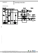
Connect the lines according to your application. When doing so,
observe chapter 4.4 Connection screen.
Item no. 50024-5-9970 · ENG · Revision 213992 · Release 2020-07-14 · Page 7 / 11
ebm-papst Mulfingen GmbH & Co. KG · Bachmühle 2 · D-74673 Mulfingen · Phone +49 (0) 7938 81-0 · Fax +49 (0) 7938 81-110 · [email protected] · www.ebmpapst.com


