For more information visit: www.eaton.com
www.eaton.com
www.eaton.com
www.eaton.com
www.eaton.com
Instructions for
VSR-Series Type 5HK
Vacuum Motor Starter
IB01301027E
Page 23
Page 23
Page 23
Page 23
Page 23
Effective: May 2008
Effective: May 2008
Effective: May 2008
Effective: May 2008
Effective: May 2008
IB01301027E
3. From the point the light flickers, rotate insulator on middle phase
bottle counter-clockwise three and twothirds turns to establish a
5.5mm open gap. Use markings on insulator to verify correct
rotation. (Two thirds turn is equal to 8 divisions that are molded
on the surface of the insulator.)
4. Slowly rotate the main shaft, closing the VI’s, until the middle
phase light is on. Adjust the insulators on the two outside
phases so that the lights on all three phases come on simulta-
neously, (DO NOT MOVE THE INSULATOR ON THE MIDDLE
PHASE) while rocking the main shaft open and closed.
5. Tighten locknuts securing threaded rod to top of each insulator.
Use bottle wrench to insure standoff insulator does not rotate
during this operation.
6. Perform test as described in section 6 on
Vacuum Integrity
Check
before returning contactor to service.
7.2 Coil Replacement
1. Remove the coil leads from terminals 5 and 6 on the control
board. Cut the wire-tie securing the coil leads to the baseplate.
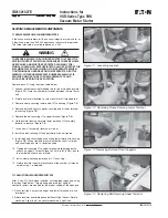
2. Remove the coil mounting angle by removing the two angle
mounting bolts located on the bottom of the contactor baseplate.
(Figure
7-7
). Be careful not to allow the angle to move abruptly
as the bolts are removed since there is pressure applied to the
angle by the return spring. Remove coil assembly from contactor.
3. Remove the locknut holding the return spring bolt on the back of
the mounting angle (Figure
7-8
). Note: After removing locknut,
count the threads protruding through the mounting angle to
insure correct length during reassembly.
4. Unscrew the spring assembly by hand and remove from the
angle (Figure
7-9
).
5. Slip the two coils from the cores.
6. Install the two new coils over the cores. (Figure
7-10
)
7. Thread the return spring assembly into the mounting angle until
the locknut under the bottom spring retainer just contacts the
angle. The number of threads protruding through the mounting
angle should be the same as counted in step 3 above. Do not
overtighten since this would compress the return spring and
prevent the proper force from being applied to the operating
plate on opening. The rear locknut for the return bolt should then
be tightened on the back of the angle.
8. Secure the angle to the contactor baseplate using the two
mounting bolts. Sufficient force must be applied to the angle to
compress the return spring and allow the threaded holes in the
angle to align with the appropriate holes in the baseplate.
9. Connect the coil leads to the appropriate terminals on the control
board. Secure the leads using a wire tie and the hole in the
baseplate to insure that the leads do not become abraised.
Before the contactor is reinstalled, verify proper operation using
test power. When power is applied, the contactor should close
cleanly. When power is removed, the moving armature should
securely contact the stop assembly.
7.3 CONTROL BOARD CHECK AND REPLACEMENT
To verify the output of the control board, apply rated control voltage
to terminals one and two.
VERIFY THAT THE APPLIED POWER CANNOT BE FED BACK INTO
ANY CPT OR OTHER CIRCUIT, WHICH MAY GENERATE DANGER-
OUS VOLTAGES.
Using a standard hand-held multimeter, check the dc output of the
board at terminals 5 and 6. The voltage should be approximately 9
to 16 volts. If there is no output, the board must be replaced. If there
is an output voltage, but it is not within this range, remove the board
and verify the dip switch settings.
To remove the board, wires connected to terminals 1, 2, 5, and 6
must be disconnected. Make certain that the wires are properly
marked before disconnecting to insure the ability to reconnect them
to the proper terminal. After the wires are disconnected, loosen the
mounting screws located at the top and the bottom of the terminal
block. The board may now be withdrawn from its mounting
compartment.
Before a new board is installed, make certain that the dip switches
are properly set. Refer to Table 4.1 and Table 4.2. Installation is the
opposite of removal.
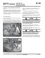
7.4 STOP ASSEMBLY REPLACEMENT
If the stop assembly becomes worn it should be replaced.
To replace, close the contactor with test power. Remove the two
bolts securing the assembly to the baseplate. Install a new
assembly. Hand-tighten bolts. Set gap between the armature plate
and stop to 0.534 in. 0.004 in. using adjustment block provided with
replacement stop assembly, torque bolts to 214 lb-in (24.2 N-M).
(See Figure
7-11
)
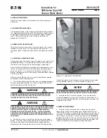
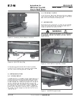
Figure 7-5 Removal of Vacuum Interrupter
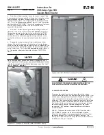
Figure 7-6 Installation of Bolt and Shunt Supports
WARNING


