6
15kV Class Padmount VisoVac™
instruction manual
MN024004EN April 2021
For information about Eaton VCP-T vacuum circuit breaker,
please use the following link here:
https://www.eaton.
com/us/en-us/catalog/electrical-circuit-protection/mv-vcp-t-
vacuum-circuit-breakers.resources.html.
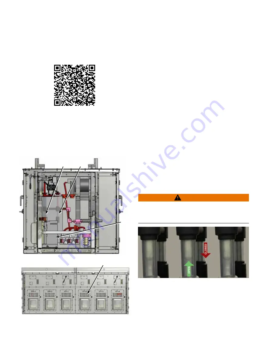
V3 – Vacuum interruption with visible isolation and
visible grounding
Switchgear designated as V3 will have vacuum interruption
capability and come with visible isolation and a visible
grounding capability. These features are mechanically
interlocked internally. V3 Style switchgear is only available in
a control front/cable rear configuration.
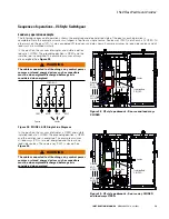
Rod viewing window
SIDE VIEW
FRONT VIEW
Ground
Isolation
VFI
Figure 12 . V3 control front/Cable rear configuration
Visible isolation
A three-pole, group-operated, non-load break, air insulated
isolation switch is located internal to the enclosure. This
feature also includes a viewing window to confirm a
physical disconnect between the source and load for that
particular switch or VFI way only. The isolation switch is a
non-load break switch and should never be used to break
load under any conditions.
Indicators are physically linked to the operating mechanism
and show what position the isolation switch is in. The
isolation switch is mechanically interlocked internally with
the vacuum interrupting load-break mechanism.
The isolation switch is also mechanically interlocked
internally with the grounding switch to prevent the
grounding switch from being operated while the isolation
switch is in the CLOSED position.
Visible grounding
A three-pole, group-operated grounding switch is included
internal to the enclosure. This feature also includes a
viewing window to confirm a physical ground connected to
incoming or outgoing bushings of the switchgear depending
on the application.
The grounding switch is equipped with mechanical
interlocks located internal to the enclosure to prevent
operation of the grounding switch while the visible isolation
switch is in the CLOSED position.
Indicators are physically linked to the operating mechanism
to show what position the ground switch is in.
WARNING
It is the duty of the operator to follow all local
procedures for proper operation of the switchgear . The
operator should always check that the bus connected to
the ground switch is NOT energized before operating .
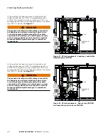
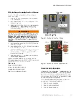
Figure 13 . V3 Series front viewing window [Isolation
(rear rods) & Grounding (front rods)]


