


5
Section IV – Principles of Operation
A. System Control
In electrohydraulic servo valve systems, the control or com-
mand and feedback elements are electrical. As indicated in
Figure 2, the command signal (which may be a tape control,
punched card, dials, push button, etc.) dictates the operation
of the servo valve to provide control of work as to sequence,
direction, velocity, position, acceleration, and so on, or a
combination of these. Feedback transducers (devices such
as potentiometers, synchros, tachometers, accelerometers,
etc.) can be used to measure results of the actual load
motion in a closed loop hydraulic circuit. The electrical feed-
back signal can then be compared electrically with the
command signal. If a difference between the feedback and
command exists, the error current which results makes a
correction to bring the system toward the desired command
input.
B. Amplifier
The input command signal and the feedback signal of a
servo system normally are both of very low power. They
must be amplified, or increased in strength, to a level which
is usable by the torque motor of the servo valve. This is done
by the servo amplifier.
C. Servo Valve
The servo valve provides a flow proportional to the electrical
current applied to it. The direction of flow is dictated by the
polarity of the DC signal. This electrical signal can be the
amplified command signal or the error signal as described
above.
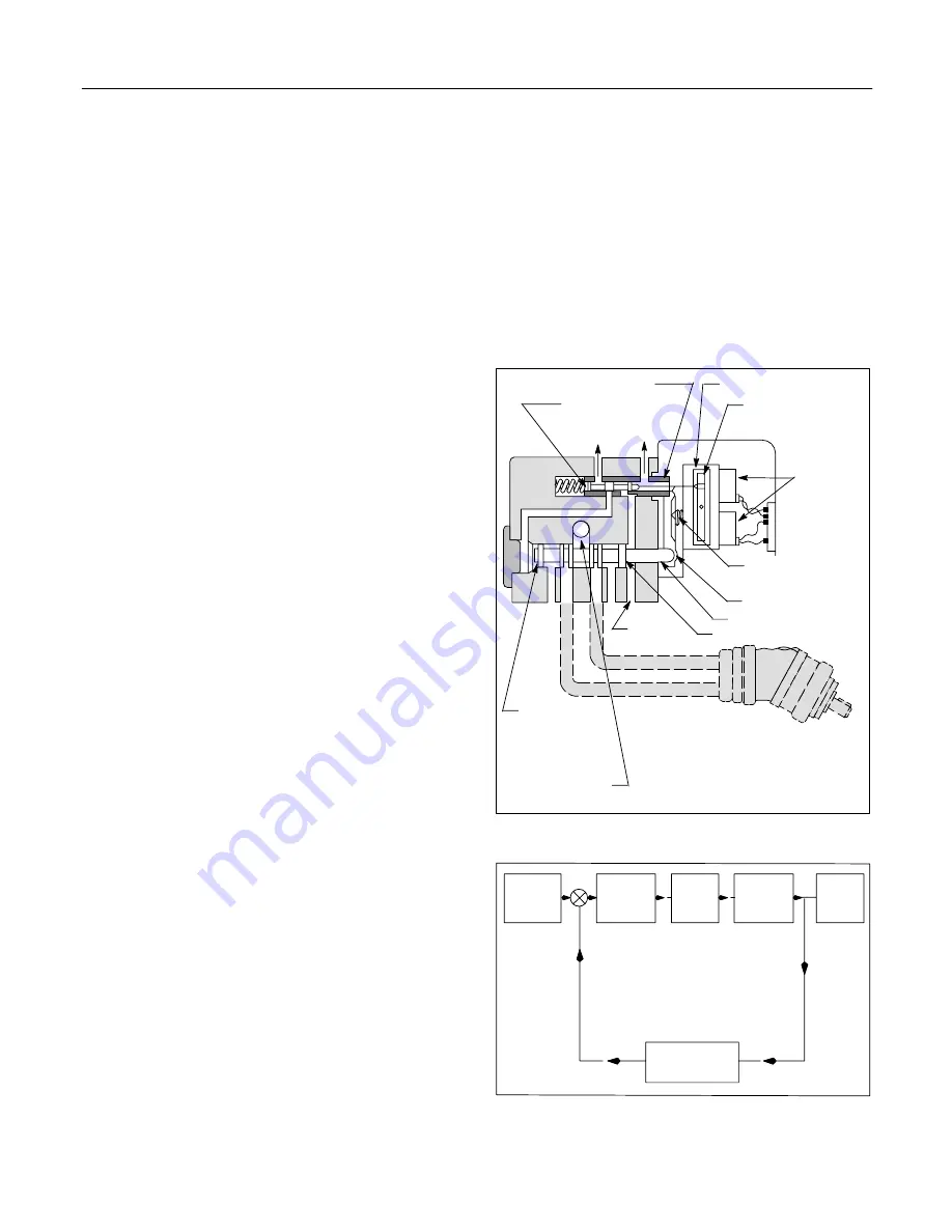
The SA4 Series servo valves consist of two stages: the pilot
stage and the main stage. As shown in Figure1, the upper
spool and sleeve comprise the pilot stage which controls the
movements of the lower main stage spool. Hydraulic fluid is
metered and directed to and from the work by the main
stage. This is accomplished in the following manner:
When the electrical signal from the amplifier directs the
torque motor to move the pilot spool, hydraulic fluid is
metered to or from the 2A end of the main spool. Control
pressure is always present against the 1A end area of the
main spool. Since the 2A end area of the main spool is twice
that of the effective area on the 1A end, the same pressure
on both ends (or greater area of force on the 2A end) will
cause the main spool to shift right. As the pilot moves to the
right, fluid is permitted to drain back to tank from the 2A end
and relieve pressure. When pressure on the 2A end of the
main spool reduces to less than one-half the control
pressure of the 1A end, the pressure at the 1A end moves
the spool to the left. Fixed position of the main spool is
achieved when the pressure in the 2A end is one-half the
control pressure at the 1A end. Movement of the main spool
is transmitted through the mechanical linkage to the pilot
valve sleeve. The main spool continues to move until the
pilot valve sleeve moves far enough to close off the flow of
control fluid.
The main spool directs the flow to either pressure port “A” or
“B” of the valve. Relationship of the spool to its stationary
sleeve determines the amount of fluid metered to and from
the motor or cylinder.
Independent control pressure can be supplied from a
separate source such as a separate pump or from the
supply pressure source using pressure reducing valves
and accumulators. A separate source for the control
pressure is preferred because:
1. It provides flexibility for trimming system to a fine point
by careful adjustment of one pressure with another.
2. It permits separate filtration of control hydraulic fluid.
3. It is less power wasting.
4. The maximum control pressure preferred is 1000 PSI
while the supply pressure may be as high as 3000 PSI.
5. It eliminates interaction of load fluctuation on pilot
spool response in critical systems.
Figure 1. Servo Valve Schematic
Pilot Stage Sleeve
Torque Motor
Pilot Spool
Torque Motor
Armature
Drain
Drain
Coils
Linkage Fulcrum
(variable)
Feedback Linkage
Main Spool
1A Spool End Area
Control
Pressure
2A Spool
End Area
Supply Pressure
(Actuator)
Hydraulic Motor
or Cylinder
Figure 2. Servo Valve System Block Diagram
Command
Signal
Servo
Amplifier
Servo
Valve
Actuator
Load
Feedback


