


6
Direction
of
Rotation
A
B
Pin
Rocker
Arm
Figure 4.
Before pressure builds up, the pressure plate is held against
the cartridge by a wave (spring) washer (Figure 3). As
system pressure builds up, shuttle valves (1 in Figure 3) in
the pressure plate permit system pressure at the inlet port to
act on the cover end of the pressure plate (chamber A). This
provides a force necessary to overcome the axial separating
forces within the rotating group. Pressure ported by these
shuttle valves is also supplied to the under side of the vanes
(through passage B).
The shuttle valve seals against one or the other of the seats
(depending on the direction of flow) and prevents pressure
fluid from escaping to the outlet port without going through
the cartridge.
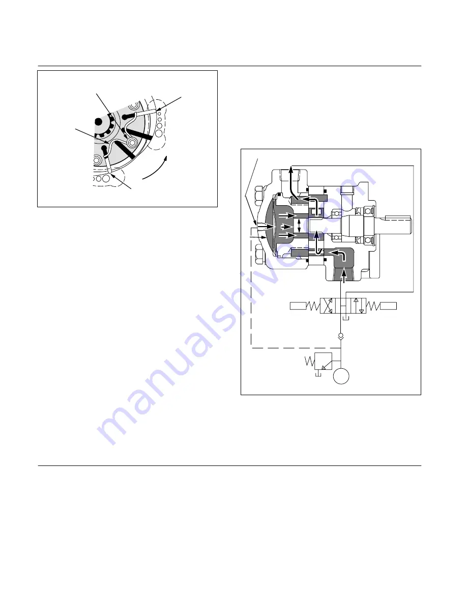
F. S2 Motors
In these motors, a pressure 30 psi higher than system
pressure is continually fed to the base of the vanes and to
the front of the pressure plate. This is accomplished by
connecting an external pressure source to the motor cover
and feeding pressure oil directly behind the pressure plate.
Rocker arms are not required, and so a pump rotor is used.
The special pressure plate has porting to feed pressure
under the vanes thus eliminating the need for shuttle valves
(see Figure 5).
Pressure 30 psi higher than system pressure is obtained by
placing a 30 psi check valve between the pump and
directional valve and sampling pressure ahead of the check
valve (see Figure 5).
ÄÄÄ
ÄÄÄ
ÄÄÄ
ÂÂ
ÂÂ
S2 Connection
No Shuttle Valve
Man
Man
30 PSI
PF
A
B
Figure 5.
Section IV
–
Installation and Operating Instructions
A. Installation Drawings
The installation drawings listed in Table 1 give correct instal-
lation dimensions and instructions.
B. Drive Connections
1.
Direct Mounting.
Motors so connected are mechani-
cally linked by shaft couplings to the work load. Care should
be exercised in tightening all flange mounting screws to pre-
vent misalignment of shaft connections.
If gaskets are used between mounting flanges of motors and
work load, they should be installed to lay flat and the same
care should be taken in tightening the flange screws evenly.
Shaft connecting devices that are specified for a particular
motor, i.e., keys, collars, or tongued shafts, must be properly
seated to avoid slippage and possible shearing of the shafts.
2.
Indirect Mounting.
Motors mounted indirectly to
work load employ the use of pulleys and
“
V
”
belts or chain
and/or spur gear arrangements. Because of slippage possi-
bilities, it is not recommended that flat belts be used. It is
important to check for correct alignment and excessive belt
tension for any drive coupling arrangement employed on
these motors. This is necessary to prevent excessive side
loads imposed on the drive shaft bearings.