
23
www.eaton.com/wireless
call toll free: 1-800-663-8806
DM-R260-0056A R1
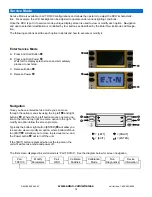
Service Mode: Run Diagnostics (continued)
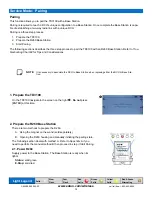
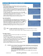
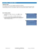
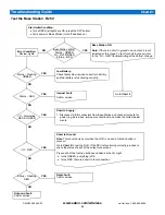
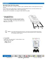
Test Controls
1. On the TD3100 navigate to the screen on the right
and press [ENTER]
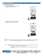
2. This
screen
displays the current values for all controls (whether in-
stalled or not). All controls are displayed as analog signals.
3. If the displayed value changes significantly when the corresponding con-
trol is moved, the control is working (The displayed values do not provide
any diagnostic information. They show a change of state when the con-
trols are moved).
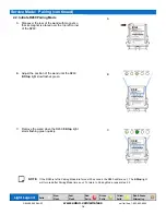
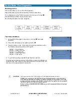
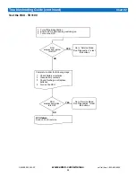
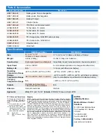
Test E-Stop
1. On the TD3100 navigate to the screen on the right
and press [ENTER]
2. The
screen
will display the current E-Stop button state.
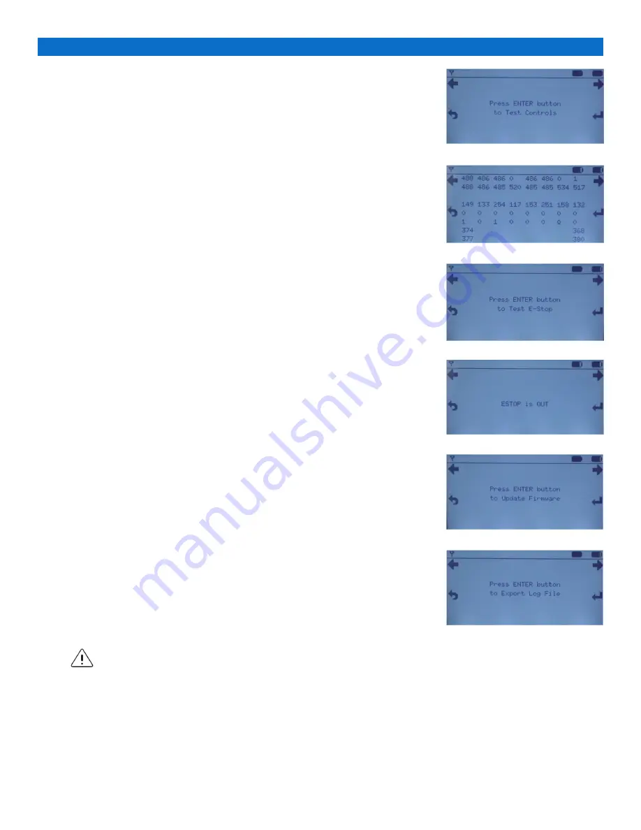
Changing the state of the E-Stop by twisting and releasing it (OUT) will
display
ESTOP is OUT
. Pushing the E-Stop in will display
ESTOP is IN
.
3. To exit E-Stop testing press [EXIT]
If the E-Stop fails to report its status correctly clean the E-Stop of any debris
and repeat the test.
If E-Stop will not function then contact you service representative for assis-
tance.
CAUTION:
Only clean a button or the TD3100 with a soft cloth lightly dampened with water.
DO NOT clean a button or the TD3100 with any sharp instruments or objects that can
cut or damage the button membrane or housing. DO NOT pour any liquids, use a hose,
or pressured water directly on the TD3100. Consult with the supplier of your equipment
if your are unsure of correct cleaning procedures.
Failure to follow CLEANING PROCEDURES may result in equipment failure and serious
personal injury.
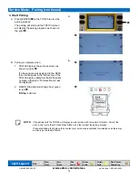
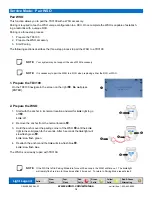
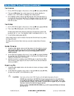
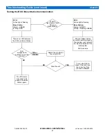
Update Firmware
1. Install the USB adaptor cable (sold separately) onto the tether connector
and plug in the USB memory stick with the upgrade files [
IMPORTANT
:
Only put the files applicable to the device being updated on the
memory stick!]
2. On the TD3100 navigate to the screen on the right
and press [ENTER]
to copy files from the USB memory stick to the device (The files being up-
dated will be displayed on the screen)
3. After file transfer is complete, press ENTER again to reset device. [Note:
The device may take longer to start up the first time as the new firmware
is being installed.]
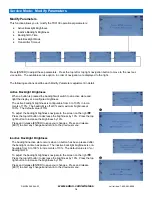
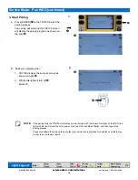
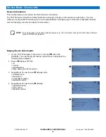
Export Log File
1. Install the USB adaptor cable onto the tether connector and plug in a USB
memory stick
2. On the TD3100 navigate to the screen on the right
and press [ENTER]
to export the log files to the USB memory stick