Sure-Lites
AtLite
Installation Instructions for the Sure-Lites SELDWTA29SD/SELDWA50SD/
ATLELDWTA100SD/ATLELDWA300SD series
Emergency Light with Self Diagnostics
IMPORTANT SAFEGUARDS
When using electrical equipment, basic safety precautions
should always be observed including the following:
•
READ AND FOLLOW ALL SAFETY INSTRUCTIONS
•
Do not use in hazardous locations, or near gas or electric
heaters.
•
Do not let power supply cords touch hot surfaces.
•
Use caution when servicing batteries. Battery acid can
cause burns to skin and eyes. If acid is spilled on skin or in
eyes,
fl
ush acid with fresh water and contact a physician
immediately.
•
Do not use this equipment for other than the intended use.
•
Installation is to be performed only by quali
fi
ed personnel.
•
Install in accordance with National Electric Code and local
regulatory agency requirements.
•
The use of accessory equipment not recommended by the
manufacturer may cause an unsafe condition.
•
Equipment should be mounted in locations and at heights
where it will not readily be subjected to tampering by un-
authorized personnel.
•
SAVE THESE INSTRUCTIONS
Maximum Mounting Height for SELDWTA29SD series: 8.6 ft.
Maximum Mounting Height for SELDWA50SD series: 18.8 ft.
INSTALLATION
1. De-energize the circuit at the junction box (J-box) where
the emergency light is to be installed.
2. Open the emergency light by inserting a
fl
at screwdriver in
the two slots on the side of the unit, then turning to sepa-
rate housing from the backplate.
3. To mount to a junction box - Knock out/drill out the appropriate
mounting pattern and the wire pass hole in the backplate
and the back gasket to
fi
t the J-box being used.
4. To mount to conduit – Unscrew the ½” NPT plug located
at the top of the
fi
xture and screw in the user-supplied
conduit hub.
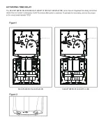
5. Once the backplate is secured, the housing can be held
in place during installation with the help of the grounding wire
(see Fig. 1 next page).
6. Connect the incoming wires to the SELDWTA29SD/
SELDWA50SD/ATLELDWTA100SD/ATLELDWA300SD series
power supply wires using the wire nuts provided. Connect the
green grounding wire for the housing. Connect the white wire to
neutral. If using 120V, connect the black wire to the hot lead. If
using 277V, connect the orange wire to the hot lead. Cap the
unused lead. Secure the emergency light to the wall and/or
junction box using installer supplied hardware.
7. Complete the battery connection and snap the cover onto
the backplate.
8. Energize AC supply. The test button should illuminate, and
LED heads will illuminate brie
fl
y when the test button is
pushed.
9. Adjust the heads as needed. The SELDWTA29SD/
SELDWA50SD/ATLELDWTA100SD/ATLELDWA300SD series
lenses utilize a highly directional beam, and the lenses can be
rotated to adjust the beams to the front or sides of the fixture
(see Fig. 2 next page).
WARNING
Risk of Fire / Electric Shock
If not quali
fi
ed, consult an electrician.
WARNING
Risk of Electric Shock
Disconnect power at fuse or circuit breaker before installing
or servicing.


