Eaton Streetworks Caretaker Скачать руководство пользователя страница 3

3

EATON    

IB500014EN 


 Installation instructions

Installation Instructions – Caretaker

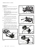
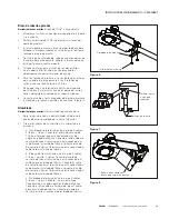
Figure 6.   

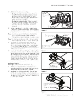
Figure 7.   

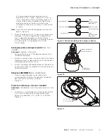
Figure 8.   

Pipe Clamp

Tools Required:

 1/2” socket wrench.

1.  Use a 1/2” socket wrench to loosen pipe clamp from 

fixture leaving enough space to allow mounting pipe to 

slide onto desired leveling step. (Figure 6.)

2.  With supply wires pulled through mounting pipe 6” to 

8”, tighten the two fixture mounting bolts using 1/2” 

socket. Tighten to 6-8 ft-lbs. 

Optional Pipe Arm

Tools Required:

 11/16” drill bit and open wrench.

1.  Establish height and location for pipe bracket and 

luminaire. 

2.  Drill an 11/16” diameter hole through the wooden pole. 
3.  Insert thru-bolt through the wooden pole, place square 

washer and nut on threaded end of thru-bolt. 

4.  Slide slotted portion of the upper bracket behind the 

head of the thru-bolt, tighten nut to draw bracket 

against pole.

5.  Drill 2 pilot holes through the two holes in the lower 

bracket. Size pilot holes appropriately for anchor 

material.

6.  Drive lag screws through the two pilot holes and 

tighten the thru-bolt and 2 lag screws with wrench. 

Torque to 25 ft-lbs.

7.  A ground lug may be included with pipe bracket. To 

install, insert carriage bolt through square hole in the 

upper bracket. 

8.  Attach ground wire around bolt, assemble washer and 

nut and tighten with wrench. (Figure 7.)

Wiring 

Tools Required:

 Flathead Screwdriver.

1.  Open fixture using screwdriver and allow access door 

to hang from ground tether. (Figure 8.) 

2.  Pull supply wires into fixture housing.

a.  Three Terminal Block (3-wire service, 2 lines, 1 

ground): Connect 1 line service lead to terminal that 

is connected to black factory-installed wire. Connect 

other line service lead to terminal that is connected 

to white factory-installed wire. Connect ground 

service lead to terminal that is connected to green 

factory-installed wire.

b.  Three-terminal Block (3-wire service, 1 line, 1 

neutral, 1 ground): Connect line service lead to 

terminal that is connected to black factory-installed 

wire. Connect neutral service wire to terminal that is 

connected to white factory-installed wire. Connect 

ground service wire to terminal that is connected to 

green factory-installed wire. 

(2) Mounting Bolts

Thru Bolt, Nut, 

And Square 

Washer

Lag Screws

Pipe Clamp Bracket

Enclosure Barrier With 

Slot For Incoming Wires

Содержание Streetworks Caretaker

Страница 1: ...es and should not be used in area of limited ventilation or inside high ambient temperature enclosures It must be stored in a dry location prior to installation Do not expose lighting fixture to rain dust or other environmental conditions prior to installation and insertion of photo control or shorting cap if so equipped Best results will be obtained if installed and maintained according to the fo...

Страница 2: ...chor material and anchor material is capable of withstanding required torque Note N Do not use holes labeled luminaire to fasten bracket to mounting surface 4 With supply wires pulled through 1 2 conduit hole 6 to 8 slide fixture down over bracket and ensure support tab is correctly positioned inside the housing wall cavity 5 Using 1 2 socket install wire shield as shown with two fixture mounting ...

Страница 3: ...t and 2 lag screws with wrench Torque to 25 ft lbs 7 A ground lug may be included with pipe bracket To install insert carriage bolt through square hole in the upper bracket 8 Attach ground wire around bolt assemble washer and nut and tighten with wrench Figure 7 Wiring Tools Required Flathead Screwdriver 1 Open fixture using screwdriver and allow access door to hang from ground tether Figure 8 2 P...

Страница 4: ...sure not to pinch any wires Tighten door screw 25 30 in lbs Optional Photocontrol Shipped Uninstalled Tools Required Flathead screwdriver 1 Loosen two flathead screws enough to allow rotation of the receptacle 2 Insert screwdriver into center slot and rotate receptacle until indicator arrow points north or desired direction Tighten screws 3 Insert the photocontrol or shorting cap into receptacle a...

Страница 5: ...4 socket or flathead screwdriver 1 If using the Drop House Side Shield with the SR Refractor slide the drop house side shield in the desired position within the SR refractor 2 Insert provided thread forming screws into refractor and house side shield and place provided O rings over screw threads to hold screws within Drop House Side Shield and SR Refractor 3 Install SR refractor in the die cast ho...

Страница 6: ...ctrique ou de la fiche de mise en court circuit si équipés Pour de meilleurs résultats respectez les recommandations d installation et d entretien suivantes Risque d incendie de décharge électrique de coupure ou d autres accidents de personne L installation et l entretien de ce produit doivent être effectués par un électricien qualifié Ce produit doit être installé conformément aux règles d instal...

Страница 7: ...s avec le matériel d ancrage et que le matériel d ancrage puis supporter le couple de serrage requis Note N N utilisez pas les trous marqués luminaire pour fixer le support de fixation à la surface de montage 4 Lorsque les fils d alimentation sont acheminés à travers un trou de conduit de 12 7 mm 1 2 po de 152 4 à 203 2 mm 6 à 8 po glissez le luminaire vers le bas et sur le support de fixation et ...

Страница 8: ...ez la rondelle et l écrou puis serrez avec la clé Figure 7 Câblage Outils requis Tournevis à tête plate 1 Ouvrez le luminaire à l aide du tournevis et laissez pendre la porte d accès de la charnière Figure 8 2 Tirez les fils d alimentation dans le boitier du luminaire a Plaque à trois 3 bornes ligne de service à 3 fils 2 lignes 1 mise à la terre Raccordez 1 fil de service électrique à la borne rac...

Страница 9: ...a plaque de l optique puis fermez la porte d accès Assurez vous qu aucun fil n est coincé Serrez la vis de la porte à un couple de 2 8 à 3 4 Nm 25 à 30 po lb Interrupteur photo électrique facultatif livré non installé Outils requis Tournevis à tête plate 1 Desserrez les deux vis à tête plate pour permettre la rotation du réceptacle 2 Insérez un tournevis dans la fente centrale et tournez le récept...

Страница 10: ...Paroi protectrice latérale pour maison avec réfracteur SR facultatif Outils requis Douille de 6 4 mm 1 4 po ou un tournevis à tête plate 1 Si vous utilisez une paroi protectrice latérale pour maison avec réfracteur SR glissez la paroi protectrice latérale pour maison vers la position désirée à l intérieur du réfracteur SR 2 Insérez les vis autotaraudeuses à formage de filet dans le réfracteur et l...

Страница 11: ...instalación e inserción del control fotográfico o la tapa de cortocircuito si está equipado Los mejores resultados se obtendrán si se instala y se mantiene de acuerdo con las siguientes recomendaciones Riesgo de incendio descarga eléctrica cortes u otros riesgos de accidentes la instalación y el mantenimiento de este producto deben ser realizados por un electricista calificado Una persona con cono...

Страница 12: ...ea capaz de soportar el torque requerido Nota N No use los orificios con la etiqueta luminaria para sujetar el soporte a la superficie de montaje 4 Una vez haya tirado los cables de alimentación de 6 a 8 pulgadas a través del orificio del conducto de 1 2 pulgada deslice la luminaria hacia abajo sobre el soporte y asegúrese de que la pestaña de soporte esté colocada correctamente dentro de la cavid...

Страница 13: ...esarias Destornillador de cabeza plana 1 Abra la luminaria con un destornillador y deje que la puerta de acceso cuelgue de la tierra Figura 8 2 Tire de los cables de suministro en la cubierta de la luminaria a Tres bloques de terminales servicio de 3 cables 2 líneas 1 tierra Conecte el cable de servicio de 1 línea al terminal que está conectado al cable negro instalado de fábrica Conecte el otro c...

Страница 14: ... la pestaña de la puerta de acceso debajo de la placa óptica y cierre la puerta de acceso Asegúrese de no pellizcar los cables Apriete el tornillo de la puerta 25 30 in lbs Fotocontrol opcional viene desinstalado Herramientas requeridas Destornillador de cabeza plana 1 Afloje dos tornillos de cabeza plana lo suficiente para permitir la rotación del receptáculo 2 Inserte el destornillador en la ran...

Страница 15: ...sa en incrementos de 90 Escudo lateral de la casa opcional con refractor SR Herramientas requeridas Zócalo de 1 4 o destornillador de cabeza plana 1 Si usa el escudo lateral de la casa con el refractor SR deslice el escudo lateral de la casa en la posición deseada dentro del refractor SR 2 Inserte los tornillos formadores de rosca provistos en el refractor y el escudo lateral de la casa y coloque ...

Страница 16: ...Todas las marcas comerciales son propiedad de sus respectivos propietarios Product availability specifications and compliances are subject to change without notice La disponibilité du produit les spécifications et les conformités peuvent être modifiées sans préavis La disponibilidad de productos las especificaciones y los cumplimientos están sujetos a cambio sin previo aviso Warranties and Limitat...

Отзывы: