

Step 6: Position the communicator and fit the fourth
pillar
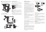
If a communicator is used, position it under the PCB.
Fit the supplied fourth pillar for the PCB (see Figure 2), and secure
the PCB to the pillar using the supplied M3x12 screw.
Figure 2. Fitting the fourth pillar
Step 7: Connect all wired devices
Connect all wired devices except the battery, as shown in Figure 3.
Step 8: Connect the battery
Note: Connecting the battery does not start the system.
Fit a 7Ah lead-acid battery in the bottom-left corner of the control
unit.
Connect the battery leads to the battery (red to positive and black to
negative), and connect the transformer lead to the PCB (Figure 3).
Step 9: Connect the mains cable
L
N
WARNING: ENSURE THAT THE MAINS
SUPPLY IS DISCONNECTED AND
ISOLATED.
Connect the mains cable to the terminal
block (Figure 4) and fit a strain-relief tie.
Do not apply power until after the lid is
re-fitted.
Figure 4. Mains connections
Step 10: Re-fit the lid, switch on and configure the
system
WARNING: During initial power-up, keypad sounders and any
internal loudspeaker may give an alarm tone. If you are working at
the top of a ladder, make sure that the sudden noise does not startle
you and cause a fall.
Re-fit the lid, then switch on the mains supply to the control unit.
Go through the initial configuration prompts and set up the system
as described in the
i-on10 Configuration Guide. You are prompted to
specify installer and user codes during initial system configuration.
PCB links and connectors
The following sections provide information about the links and
connectors shown in Figure 3.
a
Plug-by communicator port
You can connect a plug-by communicator to this port using an
optional MISC-COMPACK12 wiring harness (available separately).
By default, outputs 1-8 are 0V when active, and 12Vdc when inactive.
Please refer to the
i-on10 Configuration Guide for the default output
type used for each output and programming details.
Connect LF (Line Fail) to an output from the communicator that is
12Vdc when communicator detects that there is a communications
fault to the ARC, and 0V when no fault is present.
If a dual-path (landline and mobile) communicator is used, such as
a RedCARE STU, re-program one of the plug-by outputs to type ATS
Test, and wire that to the ATS Test input of the communicator. Also
connect Line Fail to the Line Fail output of the communicator, as
above. This is needed to comply with BSIA Form No. 175, April 2005.
The control unit generates an “ATE LF Single” alert if one network is
unavailable, or “ATE LF All” if both are unavailable.
Connect RR (Remote Reset) to an output from the communicator
that indicates to the control unit that a user can reset the system
after a system tamper. The input must be 12Vdc for at least 100ms to
indicate the reset, and 0v normally. For further details, see “Remote
Reset (Redcare Reset)” in the
i-on10 Configuration Guide.
Note: During system commissioning, confirm with the ARC that the
communicator is working correctly.
b
System bus
Up to four keypads can connect to the system bus. The installation
instructions supplied with each keypad provide details of how to
install the device. The address of each device is set by the control
unit, as described in the
i-on10 Configuration Guide.
Please refer to “Step 3: Install cabling” for guidance about cabling.
See also “RS485 bus termination link”.
c
Loudspeaker connections
If fitted, a loudspeaker mimics alarm tones and repeats setting and
entry tones. The loudspeaker must be a minimum of 16 Ohms.
Note:
• A loudspeaker is not a warning device as described by EN50131-4.
• You can set the loudspeaker volume from the Installer menu.
d
Open-collector (wired) output
The open-collector transistor output can be used to switch external
equipment on or off. By default, the output is 12Vdc when inactive
and 0V when active (this can be reversed from the Installer menu).
e
Siren/strobe connections
Please refer to the installation instructions provided with the siren/
strobe unit for connection details.
f
Wired zone connections
You can connect up to 10 wired detectors (0 to 9) to the control unit
using the Fully-Supervised Loop (FSL), 4-wire Closed Circuit (CC) or
2-wire CC wiring method (Figure 5). You must use the same method
for all detectors. If 4-wire CC is used, the number of zones is halved
and are numbered 1-5. To maintain ten 4-wire CC zones (0-9), fit an
ADP-10CC board and configure the resistance setting of each zone as
2k2/4k7.
For any method, the total wiring and switch resistance must be less
than 100 Ohms (EOL resistor shorted in the case of FSL).
By default, the system assumes normally-closed contacts. Detectors
with normally-open contacts must be programmed with the
“Inverted” attribute set.
Please refer to the
i-on10 Configuration Guide for wiring details if
you want to use two detectors per zone.
Z0
Z1
EOL
Zone 1
Zone 0
Z1
Z0
Z1
Z0
Tamper Zone 1
Alarm Zone 1
Zone 0
Zone 1
4-Wire CC Wiring
2-Wire CC Wiring
FSL Wiring (default)
Supported resistor values (± 5%):
EOL Alarm
2k2
4k7 (default)
1k0 1k0
2k2 2k2
4k7 4k7
Alarm
Alarm
Tamper
EOL
Tamper
Z0
Z1
Tamper
Tamper
Alarm
Alarm
8k2
8k2
8k2
8k2
FSL Wiring, with 8k2 resistors
Figure 5. Zone wiring
g
Kick-start link
Ordinarily, the control unit starts only after the mains supply is
switched on, even if a battery is connected. If you want to operate
the control unit temporarily using only the battery, start the control
unit by briefly shorting this link.
h
Reset codes link
You can use this link to reset the installer and all user codes (e.g.
in the event that codes have been forgotten). All proximity tags are
also deleted. This link can be enabled or disabled by a setting in the
Installer menu. Please refer to the
i-on10 Configuration Guide for
further details.
i
RS485 bus termination link
If the control unit uses a single daisy chain to connect keypads and
is at one end of the chain, fit a jumper across this link in the control
unit and in the last keypad on the bus. RS485 termination can
improve performance in electrically noisy environments. The
i-on10
Configuration Guide gives further guidance.
Maintenance
Inspect the control unit once or twice per year as part of general
inspection of the whole system. At the control panel, check for any
damage, test the battery, and check the action of the tamper switch.
Please refer to the
i-on10 Configuration Guide for general guidance
about maintaining the whole system.
Figure 3. Control unit PCB
1
2
3
4
5
6
7
8
LF
RR
0V
12V
Z0
Z1
Z2
Z3
Z4
Z5
Z6
Z7
Z8
Z9
A
B
+12V
0V
0V
0V
A
B
+12V
0V
12V AUX
12V AUX
LS-
LS+
OP3
OP2
OP1
TR
BELL/SIREN
STROBE
12Vdc
0V
TR
e
Siren/strobe unit. Note:
If a siren/strobe unit is not
fitted, connect TR to 0V.
c
L
oudspeak
er
h
Reset
codes link
a
Plug-by
communicator port
For engineering use only
f
Zones 0 to 9
0V/12Vdc
outputs
d
Open-
collector output
b
Ststem bus
(Max 4 keypads)
Keypad 1
i
RS485
termination
g
Kick-start link
Connect transformer
Connect battery lead
Fit supplied
pillar


