


Quick Start Instructions
ConnectUPS-E Models
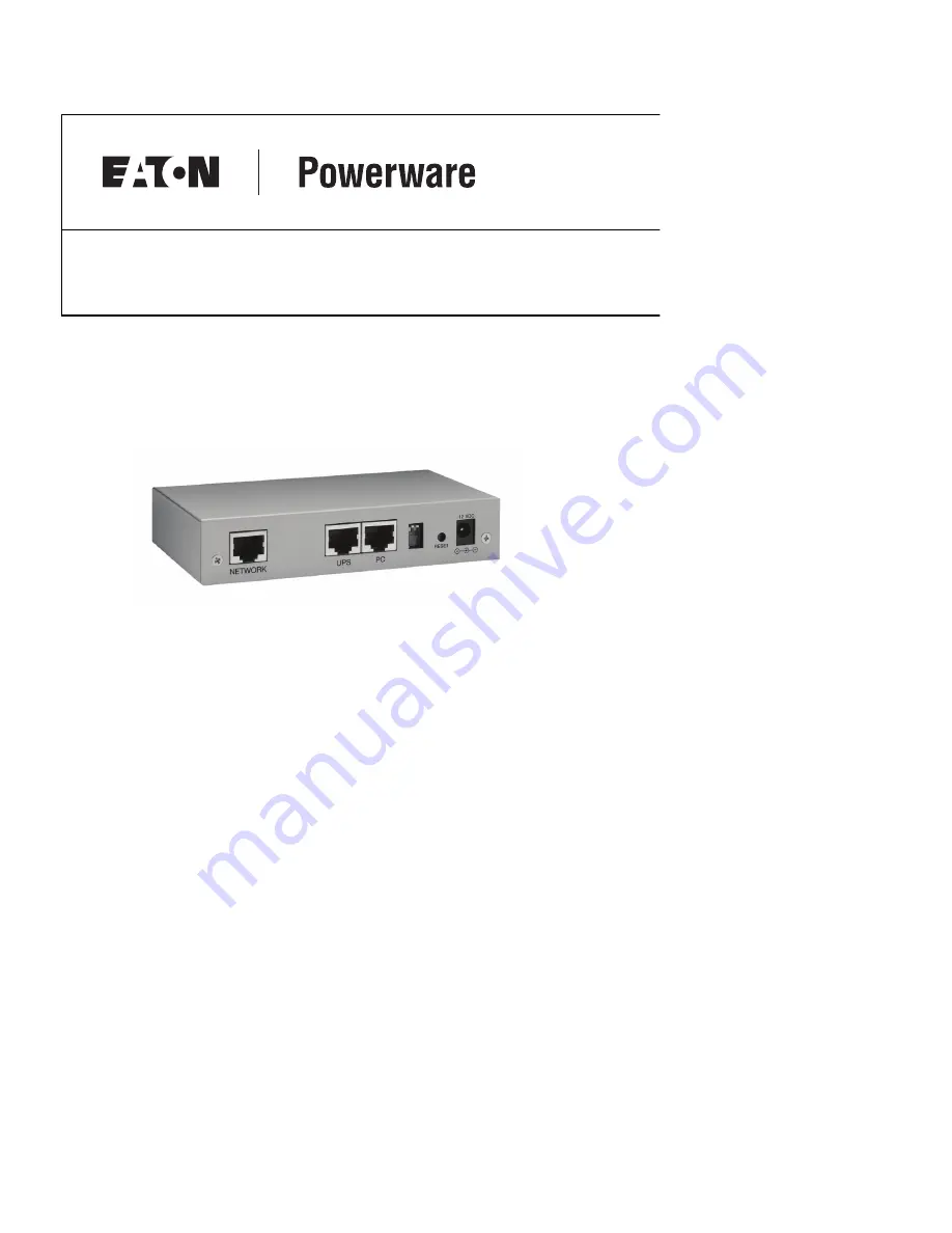
Package Contents
S
Powerware ConnectUPS
t
Web/SNMP Adapter
S
Male DB-9 to RJ-45 Serial Cable with Detachable DC Power Cable
S
Female DB-9 to RJ-45 Serial Cable (labeled “PC”)
S
External Power Supply with Detachable Power Cord
S
Software Suite CD with User Guide PDF
S
Quick Start Instructions
S
Ethernet Cable
®