Modbus Registers
Eaton Power Xpert Gateway PXGX PDP Card User’s Guide 164202122—Rev 1
65
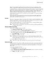
Calculating Breaker Register Numbers
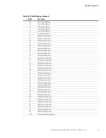
Table 11 shows the sample register numbers for Breaker #1. There can be many breakers in a panel. Determine
the corresponding register numbers for other breakers in the panel by using the following formula:
Breaker register # = Breaker #1 re ((Breaker # – 1) x 200))
This formula works for any register. For example, for Breaker #1, the register number of “Watts Phase A” is
1055. The corresponding address for Breaker #18 is:
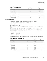
Breaker Alarms (FC 02)
There are two alarms for each circuit breaker: Overload Warning and Overload. Each alarm has a unique address
similar to the data registers, but these alarms are not data registers. The alarms are discrete inputs and are read
using FC 02 in the Modbus program.
AC MAX Current Phase B
1045
FLOAT
4
AC MAX Current Phase C
1047
FLOAT
4
Percent FL Current A
1049
FLOAT
4
Percent FL Current B
1051
FLOAT
4
Percent FL Current C
1053
FLOAT
4
Watts Phase A
1055
FLOAT
4
For example:
Breaker #2 starts at 1200:
1000 + ((2 – 1) x 200)
1000 + (1 x 200)
1000 + 200
1200
Breaker #3 starts at 1400:
1000 + ((3 – 1) x 200)
1000 + (2 x 200)
1000 + 400
1400
Breaker #14 starts at 3600:
1000 + ((14 – 1) x 200)
1000 + (13 x 200)
1000 + 2600
3600
1055 + ((18 – 1) x 200)
1055 + (17 x 200)
1055 + 3400
4455
Table 12. Breaker Alarms (FC 02)
Name
Coil/Status Address
Data Type
Branch Breaker 1 Overload Warning
1000
BOOL
Branch Breaker 1 Overload
1001
BOOL
Table 11. Breaker #1 Sample Data Registers (FC 04) (Continued)
Name
Register
Data Type
Bytes
Содержание Power Xpert PXGX PDP
Страница 1: ...Eaton Power Xpert Gateway PXGX PDP Card User s Guide ...
Страница 76: ... 164202122 164202122 1 ...


