background image

Power Xpert Insight Gateway 

Quick Start Guide

20

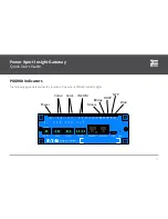
Power

: Lights green when power is supplied to the gateway. 

Com2/Com1

: Transmit (green) and receive (yellow) flash during 

data transfer between the gateway and Modbus devices. Trans

-

mit indicates data sent to the connected device, receive indicates 

data from the connected device.

INCOM

: Transmit (green) and receive (yellow) flash during data 

transfer between the gateway and INCOM devices. Transmit in

-

dicates data sent to the connected device, receive indicates data 

from the connected device.

Status

: Indicates the health of the gateway. The LED is first red 

then blinks an alternating pattern of red and green during boot

-

up. It lights solid green when the system is booted and operating 

normally. Red indicates a major fault.

Bridge

: Lights yellow when the Ethernet ports are bridged to

-

gether for daisy chaining. This is the default behavior.

DHCP

: Blinks yellow when the gateway is attempting to obtain 

an IP address via DHCP. It lights solid yellow after the gateway 

obtains an IP address. Not lit indicates that a static IP is in use.

NTP

: Off when NTP is not enabled. Blinks green when the gate

-

way is attempting to synchronize with one or more NTP servers. 

It lights green when it has synchronized with an NTP server. 

Web

: Lights red when one or more browsers are currently ac

-

cessing the gateway’s web server. 

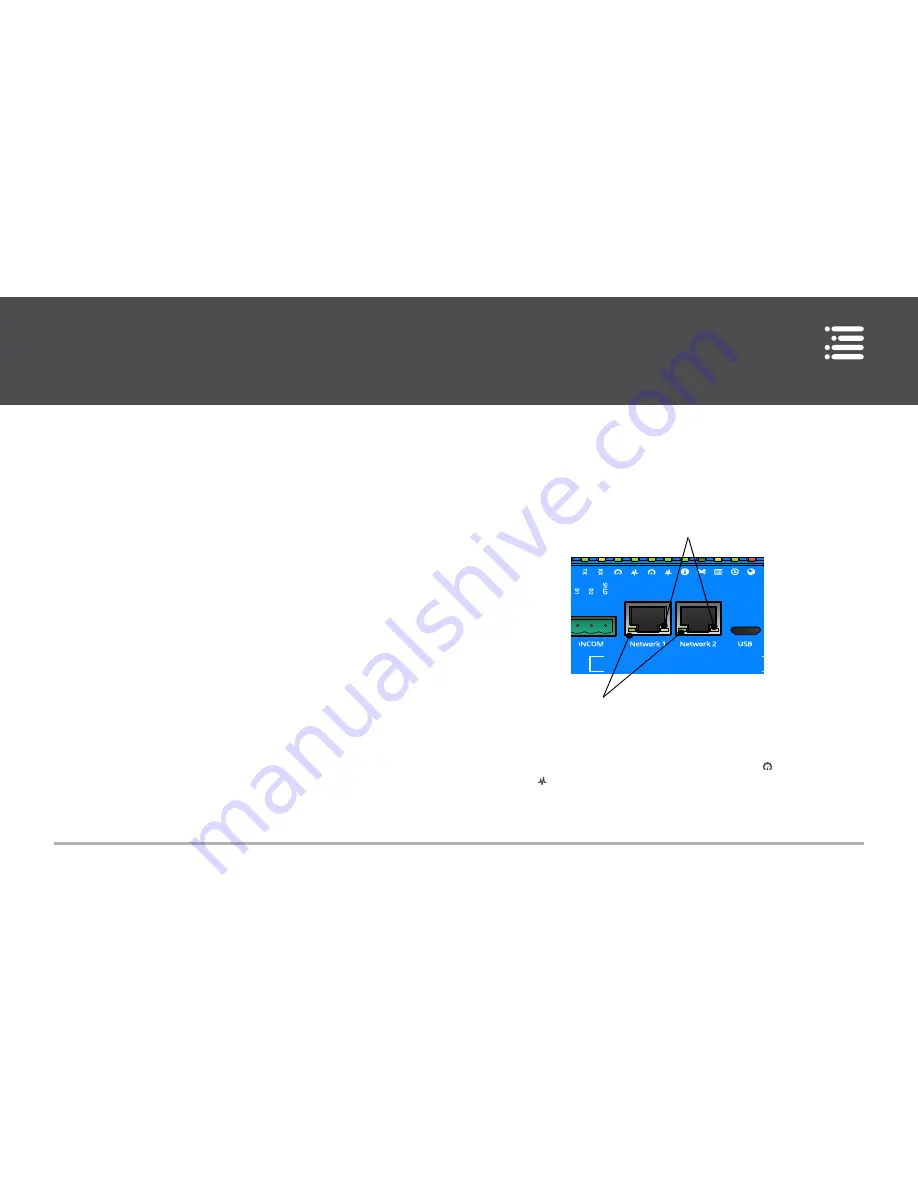
Ethernet Status LEDs

Power Xpert Insight

Gateway

COM 1

Activity

Link Speed

Each Ethernet RJ45 connector has a link speed indicator (left) 

and an activity indicator (right). These are also shown on the top 

row of indicators, with the link speed labelled as   and activity 

labelled as  . They have the following meanings:

Link speed

: off=no link, yellow=100Mb, green=1000Mb.

Содержание Power Xpert Gateway 900

Страница 1: ...Power Xpert Insight Gateway Quick Start Guide 1 Version 3 1 Power Xpert Gateway 900 Quick Start Guide...

Страница 2: ...uration 2 Mounting 3 Grounding 4 Connecting the Power Supply 5 Connecting a PC via the USB Cable 6 Connecting Devices 9 Connecting a PXG900 to the Ethernet LAN 9 Configuring the Gateway 10 Settings 12...

Страница 3: ...peration and maintenance of this device WARNING Indicates a hazardous situation which if not avoided could result in death or serious injury CAUTION Indicates a hazardous situation which if not avoide...

Страница 4: ...the PXG900 Ethernet LAN port to the Ethernet LAN system such as to a router or switch Twisted pair cabling for communications between the Mod bus RTU and INCOM networks and the PXG900 communica tions...

Страница 5: ...ia a DIN rail the adapter is shipped with the gateway along with appropriate mounting machine screws You can adjust the DIN rail adapter to allow vertical or horizontal mounting default by removing th...

Страница 6: ...ttach these screws to rotate for vertical mounting 1 97 50 2 023 51 402 0 556 14 12 Side View DIN Rail Adapter Mounting Dimensions Grounding The GND of the 24 VDC 0 3 A minimum Class 2 power supply sh...

Страница 7: ...rounding the PXG900 Wiring Connections Connecting the Power Supply 1 Connect the two power supply leads from a 24 VDC 0 3 A minimum class 2 power supply to the two pin Phoenix connector shipped with t...

Страница 8: ...ttp eaton com PXG To find it 1 Navigate to the eaton com PXG site 2 Choose the link for Power Xpert Gateway PXG900 3 Choose Documentation tab 4 Choose Software Downloads 5 Choose the PX USB Configurat...

Страница 9: ...r for driver software 6 Choose Browse The Locate File window opens 7 Locate and select the folder containing the powerxpert inf file 8 Choose Open The folder displays in the Search for driver software...

Страница 10: ...ftware displays select Install this driver software anyway 11 To verify that the device is installed Go to Control Panel Hardware and Sound Devices and Printers Device Manager Expand Network adapters...

Страница 11: ...ipconfig all 14 Verify that the assigned IPv4 address assigned to your PC is in the 192 168 200 x range where x is typically 1 Connecting Devices Power Xpert Insight Gateway Power Modbus Ethernet INCO...

Страница 12: ...eb interface 1 Open a browser and navigate to the following address http 192 168 200 101 2 You ll be prompted to enter a user ID and password The default for both is admin 3 You should see something l...

Страница 13: ...atic IP address in the PXG900 setup screens This is the recommended approach If you choose this approach note this IP address on the label publish it to the users and make certain it s reserved in you...

Страница 14: ...er the connectors Settings Under Settings you can configure Date and Time Localization Access Control enable disable ports and enable trusted hosts Modbus TCP if enabled Look in the upper right of the...

Страница 15: ...P HTTPS and Modbus TCP 80 443 and 502 respectively You can disable enable or change these ports You can also set each port so that it can only be used to access the PXG900 through a trusted host name...

Страница 16: ...uration you can set up the way the server responds to client requests For example you can allow the server to respond to write commands where appropri ate or not to allow them Configuring Device Commu...

Страница 17: ...nnecting the PXG900 to either a twisted pair Modbus or a twisted pair INCOM cable make sure that you observe the proper polarity when wiring the cable to one of the three pin Phoenix connectors provid...

Страница 18: ...the PXG900 Note If needed add an external 100 ohm resistor 1 Attach one of the three pin Phoenix connectors shipped with the PXG900 to the Modbus twisted pair cable 2 Connect the Modbus cable to the C...

Страница 19: ...r to either Com1 or Com2 2 Choose the Network tab 3 Choose Edit 4 Choose Add Device under the appropriate COM port col umn 5 Select Meters under Family 6 Select IQ 200 Series under Model Series 7 Sele...

Страница 20: ...INCOM 4 Select Protection under Family 5 Select Digitrip Breaker under Model Series 6 Select Digitrip 1150 under Model 7 Enter a name such as Digitrip 1150_1 under Name 8 Set the Serial Address 1 FFF...

Страница 21: ...ight Gateway Quick Start Guide 19 PXG900 Indicators The following figure details what the function of the various PXG900 indicator lights Power Xpert Insight Gateway Power Com2 Web NTP DHCP Bridge Com...

Страница 22: ...ajor fault Bridge Lights yellow when the Ethernet ports are bridged to gether for daisy chaining This is the default behavior DHCP Blinks yellow when the gateway is attempting to obtain an IP address...

Страница 23: ...boot the PXG900 or reset the gate way to its default settings you can use the Reset switch To access the switch use a small bent paper clip Momentarily press the switch less than three seconds to rebo...

Страница 24: ...RIOR WRITTEN CONSENT OF EATON IN THE CASE OF CONFLICTING CONTRACTUAL PROVISIONS THIS NOTICE SHALL GOVERN THE STATUS OF THIS DOCUMENT DISCLAIMER OF WARRANTIES AND LIMITATION OF LIABILITY The informatio...

Страница 25: ...poration Electrical Sector 1000 Cherrington Parkway Moon Township PA 15108 United States 877 ETN CARE 877 386 2273 Eaton com pxg 2015 Eaton Corporation All Rights Reserved Printed in USA March 2015 MN...

Отзывы: