CHAPTER 8 - PXG200E CONFIGURATION WEB PAGE
EATON
PXG200E User Manual • IM02603001E
Rev 5, 11-May-2012 • Firmware Version 5.03:3835
76
13.
The screens illustrated in
and
contain items
that
can be entered by the user and the screen illustrated in
are
automatically assigned by the PXG200E. For clarity, these items are
listed separately as
Items Entered By User On This Page on
,
Device Configuration Tabs on page 77
and
Automatically Assigned By PXG200E on page 78
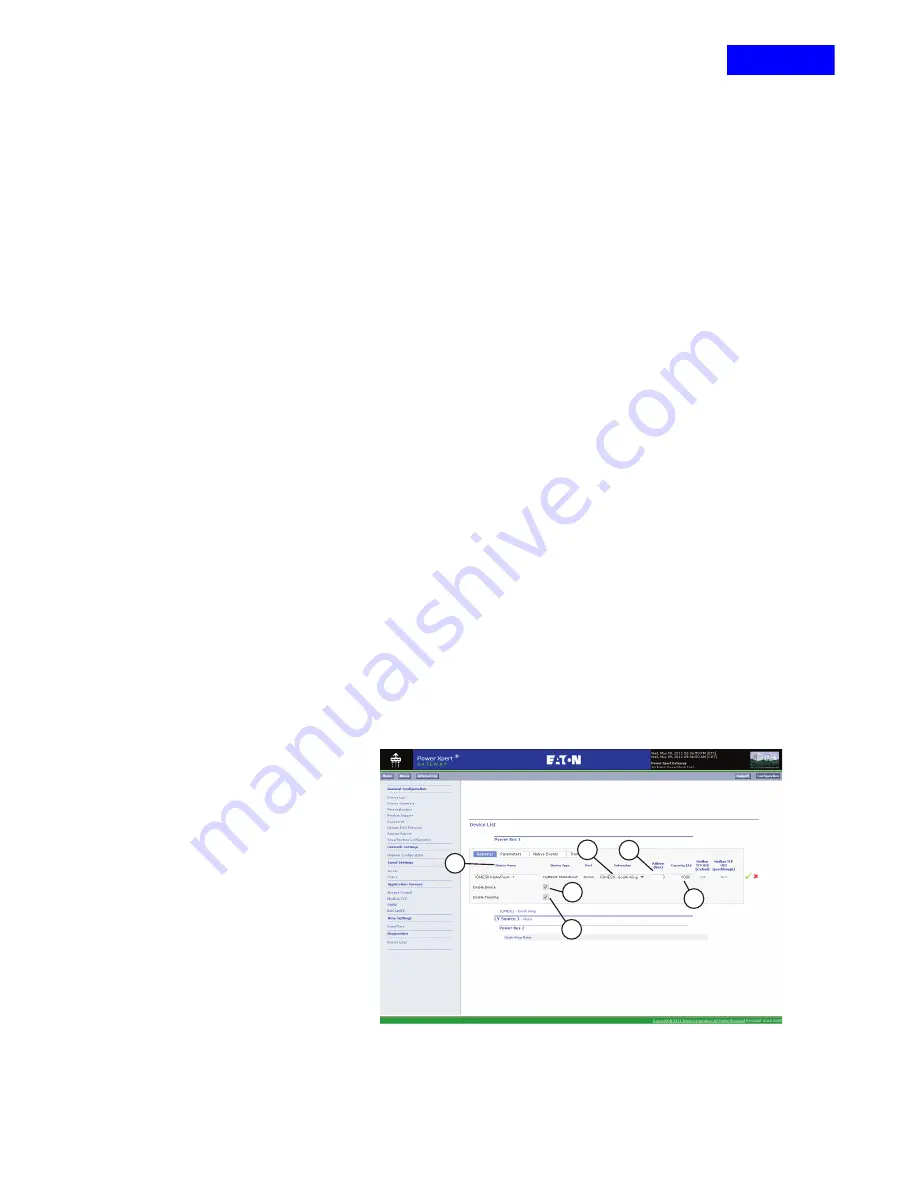
Items Entered By User On This Page
•
Name
– Enter the name of the Main as you want it to
appear on PXG200E web pages. Maximum number of characters is
30.
•
Submaster
–
For field devices connected to a
submaster, select the submaster the field device will be
connected to. In this example it is IQMESII Submaster - North
Wing.
•
Address (Hex for INCOM devices; decimal for Modbus RTU or QCPort
devices)
– Enter the address of the trip device or
meter. Each device on the network has a unique address.
•
Capacity (A)
(Figure 74, D)
– Enter the current carrying capacity in
amps for the Main you are adding. The PXG200E uses this value to
calculate the percentage of current capacity that is used by a
particular device. It is not used to provide an alarm. The default value
is 1000 A. When you configure a particular device, it is important to
enter its amp rating to ensure a meaningful value is provided when
you view the associated screen.
•
- This box must be checked to allow this
device to be polled. If this box is unchecked, the device will no longer
be displayed, trended, logged or otherwise communicated.
•
Enable Trending
(Figure 74, F)
– Click this box to enable trending for
this device. See
for details on this
feature.
NOTICE: If you are not configuring
to save the entries.
Figure 74
PXG200E_244
A
D
C
B
E
F
RETURN


