13
Installation
Instruction manual—single-phase power conditioners
IM01002005E September 2015 Eaton.com
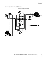
Figure 2-3: Wiring diagram for 3.5 kVA T800R (120 Vac input and output, 60 Hz)
Note:
3 .5 kVA 120 Vac load currents (X1–N or X2–N) should not exceed 50% of the unit’s rated power @ 120 Vac .
Neither duplex receptacle should be loaded more than 14 .5 A .
Figure 2-4: Wiring diagram for 3.5 kVA T800R (208/240 Vac input and 120 Vac output, 60 Hz)
Note:
3 .5 kVA 120 Vac load currents (X1–N or X2–N) should not exceed 50% of the unit’s rated power @ 120 Vac .
Neither duplex receptacle should be loaded more than 14 .5 A .

