Eaton PDI Revit Model
P-164001110—Rev 01
11
C
Chhaapptteerr 44 P
Poow
weerrW
Waavvee 22 B
Buuss S
Syysstteem
m M
Mooddeellss iinn R
Reevviitt P
Prroojjeecctt
You can create PowerWave 2 Bus System models in Revit Project for an vertical straight bus run. The following
instructions provide a quick guide to assembling models from PowerWave 2 Bus System component models.
The methodology for assembling bus runs in Revit is the same for all amperages, but parts must be matched
by amperage. PowerWave 2 Bus Systems are available in 250A, 400A, and 800A systems. Part models are
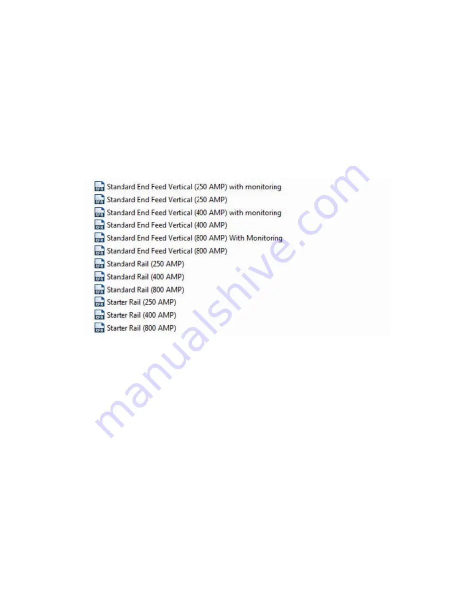
listed by part name and amperage. Choose the part model corresponding to your bus run’s amperage. For
example, when “Standard End Feed” is specified, choose “Standard End Feed (250A)” or other amperage
choice from the model list, as appropriate for your bus run.
Figure 9. PowerWave 2 Bus Run Model List with Amperages
44..11
S
Sttaannddaarrdd EEnndd FFeedd
1.
Begin by importing the standard End Feed model for your bus run’s amperage. There are two model
choices: Standard End Feed with Monitoring and Standard End Feed without Monitoring.


