Eaton LumaWatt Скачать руководство пользователя страница 2

2

EATON    

 IB512003EN


 Installation instructions

Installation Instructions - LumaWatt Remote Sensor

INSTALLATION

This lighting fixture has been shipped complete with one 

of several mounting options. Please follow the installation 

instructions specific to the catalog part that you ordered.

Tools required

Ratchet, a shallow 3/4” socket and 1/4 hex nut driver; 3/8” 

Allen drive for 1/2” inch bolt; #2 Phillips head screw driver; 

torque wrench.

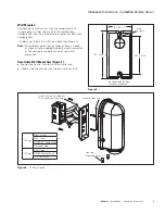
Pole Mount (Figure 1.)

The housing mounts standard to a square pole using the 

toggle bolts supplied. A round Pole mount adapter (included) 

mounts housing to a 4”- 6” round pole. A 4” pole is the 

minimum recommended.
1.  Mount toggle bolts to pole by inserting the toggle into 

the pole. If using a round pole mount adapter (optional) 

shown, install toggle through the 1/2” holes first.  

Cinch up collar against pole and remove finger tabs. 

Squeezing the tabs will shear them at the cinch collar. 

(Figure 2.)

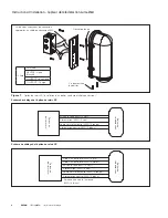
2.  Fasten housing mounting plate, slot facing downward, 

with 2 x ¼”-20 hex bolts as shown. Tightening torque 

shall be 50 in-lbs. (Figure 3.)

3.  Route and attach wires per wiring diagram. Feed wires 

through the mount plate and feed wires through the 

pole. 

ote:

N

3’ of leads are provided extending outside the 

housing. (Figure 4.)

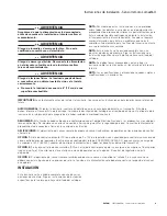
4.  Insert wires into the pole as you place the housing on 

the mount plate. The bracket on the inside fixture and 

lanyard allow for hanging the housing during installation. 

ote:

N

Do not to pinch the lanyard cable when installing 

the housing. Once the housing is in position, tighten 

using (2) set screws. Tighten until screw is bottomed 

out.

Figure 1.   

Figure 2.   

Figure 3.   

5.  Verification. Once powered a LED indicator under the 

sensor lens will glow continuous green, indicating 

that the sensor is ready for commissioning. See the 

LumaWatt Admistrators Guide or Lumawatt installation 

sheet for troubleshooting information.

Square Pole  

Mount

Round Pole  

Mount

30” [760mm]

Maximum 

1-1/2” [38mm]

Diameter Hole

(2) 1/2” [13mm]

Diameter Holes

4-9/16” 

[117mm]

2-1/2” [64mm]

2-1/16” [53mm]

After Tabs 

Broken Flush

Fingertabs 

Aligned Top 

and Bottom

Shown with 

Tabs Before 

Breaking Off.

Collar Side  

Flush

UP

1/4-20 X 1.5” 

Hex Bolt

Wall Plate with 

Gasket Installed

Slot Facing Down

Figure 4.   

Housing 

Mounting  

Screws

Lanyard 

Hook Tab

Lanyard 

Hook Tab

Housing 

Mounting 

Screws

Содержание LumaWatt

Страница 1: ...mp to 16 amp load depending on voltage Power monitoring is not available for this option Dimming control not available OPTION 3 The remote sensor housing can also be used as a repeater or hopper in wh...

Страница 2: ...in lbs Figure 3 3 Route and attach wires per wiring diagram Feed wires through the mount plate and feed wires through the pole Note N 3 of leads are provided extending outside the housing Figure 4 4...

Страница 3: ...gle gang wall box Figure 5 for compatible box configuration See the wiring diagrams below for both relay configurations CR dimming Figure 6 or SR non dimming Figure 7 Note N For outdoor applications o...

Страница 4: ...Red 18awg Neutral In White 12 awg Neutral Out to Luminaire White 18 awg Pole or Wall Box Remote Housing Ground Green 12 awg Wiring Diagram SR Relay Option Line In Black 12 awg Line Out to Luminaire R...

Страница 5: ...es options de relais n a tre connect e L alimentation n aura qu tre branch e au capteur pour qu il fonctionne AVERTISSEMENT Assurez vous que l alimentation lectrique soit HORS TENSION avant de commenc...

Страница 6: ...z les selon le sch ma de c blage Faites passer les c bles par la plaque de montage et acheminez les par le poteau Remarque R Une longueur de 91 44 cm 3 pi de fils est fournie l ext rieur du bo tier Fi...

Страница 7: ...rt NEUTRE Ligne Blanche COURANT Ligne Noire Install au mur Le bo tier peut s installer sur un mur directement sur un bo tier mural standard Figure 5 pour une configuration compatible Consultez le sch...

Страница 8: ...nc Sortie neutre vers le luminaire AWG 18 blanc Poteau ou bo tier mural Bo tier de t l d tection Mise la terre AWG 12 vert Sch ma de c blage de l option de relais SR Alimentation AWG 12 noir Sortie ve...

Страница 9: ...o tambi n puede usarse como un repetidor o saltador en cuyo caso no se deber conectar ninguna de las opciones de rel La tensi n en la alimentaci n solo deber conectarse respecto del sensor que operar...

Страница 10: ...aje y luego a trav s del poste Nota N Se incluyen 3 0 91 cm de cables que se extienden por fuera del alojamiento Figura 4 4 Inserte los cables en el poste a medida que coloca el alojamiento en la plac...

Страница 11: ...amiento para una mayor protecci n impermeable Brazo de montaje ajustable para pared Figura 4 Cable neutro del lado de la alimentaci n con cable blanco de la luminaria Cable de tensi n de l nea del lad...

Страница 12: ...SR se muestra cableado e instalaci n de caja de salida nica Tornillos de montaje del alojamiento Leng eta del gancho de amarre CONEXI N A TIERRA VIVO ENTRADA VIVO carga NEUTRO Figura 7 12 AWG Verde C...

Страница 13: ...13...

Страница 14: ...14...

Страница 15: ...15...

Страница 16: ...odas las marcas comerciales son propiedad de sus respectivos propietarios Product availability specifications and compliances are subject to change without notice La disponibilit du produit les sp cif...

Отзывы: