background image

 34007724IT/AD - Page 11

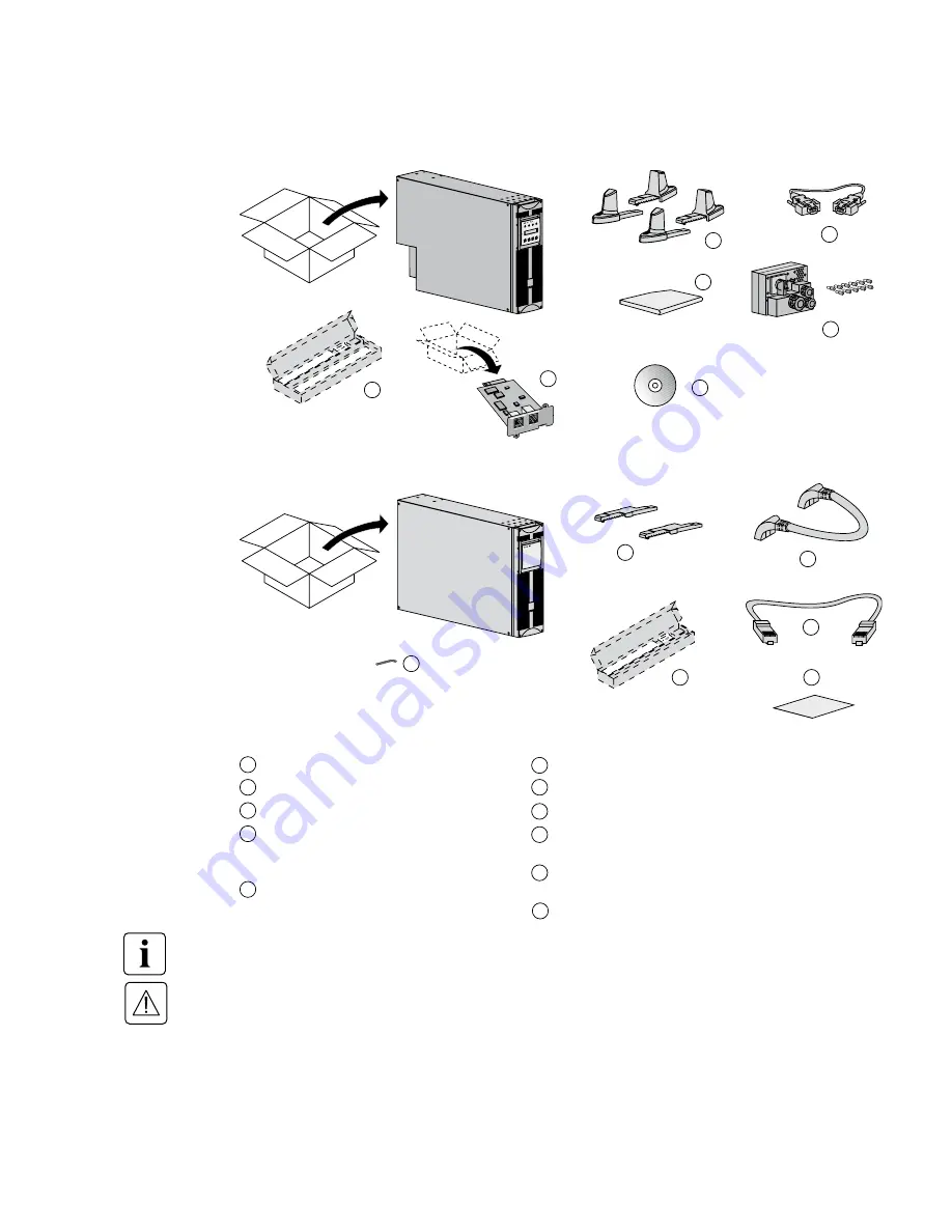
2.1 Apertura dell’imballaggio e verifica del contenuto


Piedini di sostegno.


Cavo di comunicazione RS232.


Manuali di installazione e d’uso.


Guide telescopiche per montaggio in  


uno slot da 19" (optional, oppure di  


serie nella versione

 Network Pack

).


CD-ROM 

Solution-Pac

.


Estensioni per i piedini di sostegno.


Cavo batteria.


Cavo di rilevamento batteria.


Morsettiera estraibile degli ingressi/uscita con  


11 terminazioni di cablaggio.


Scheda di rete (optional, oppure di serie nella  


versione 

Network Pack

).


Chiave BTR.

Modulo di potenza

Modulo batteria

2. Installazione

È necessario che gli imballaggi siano smaltiti in conformità con le normative in vigore in materia di rifiuti. 

Inoltre, su di essi sono riportati simboli di riciclaggio utili per facilitare la raccolta differenziata dei materiali.

All’interno del modulo di potenza e del modulo batteria è presente un voltaggio pericoloso. Pertanto, 

qualsiasi intervento su questi moduli deve essere effettuato da personale debitamente qualificato.

22

22

23

23

24

24

25

24

26

26

30

30

31

31

25

25

32

32

27

27

28

28

29

29

Содержание EX RT 5 3:1

Страница 1: ...www eaton com Installation and user manual EX RT 5 3 1 EX RT 7 3 1 EX RT 11 3 1 English Fran ais Deutsch Italiano Espa ol Nederlands...

Страница 2: ...3400772400 AD...

Страница 3: ...www eaton com Installation and user manual EX RT 5 3 1 EX RT 7 3 1 EX RT 11 3 1...

Страница 4: ...t may cause radio interference in which case the user may be required to take additional measures If the device must be installed in overvoltage category III or IV environments additional upstream ove...

Страница 5: ...Power or battery module rack mounting optional rail required 14 2 4 Communication ports 16 Connection to the RS232 communication port 16 Connection to the communications port by relays 16 Remote Powe...

Страница 6: ...Transfer to battery power 29 Threshold for the low battery warning 29 End of backup time 29 3 5 Return of Normal AC source 29 3 6 Shut down 30 4 Maintenance 4 1 Troubleshooting 31 4 2 Hot swapping the...

Страница 7: ...odule EX RT 5 7 11 Dimensions in mm inches H x W x D EX RT 5 EX RT 7 EX RT 11 EX RT EXB 7 EX RT EXB 11 444 x 131 x 635 Dimensions in mm inches H x W x D EX RT 5 EX RT 7 EX RT 11 EX RT EXB 7 EX RT EXB...

Страница 8: ...ry module connectors to the UPS or to other battery modules Manual Bypass switch Output terminal block Normal AC source circuit breaker Normal AC source terminal block Bypass AC source terminal block...

Страница 9: ...or Power module mounting in 19 enclosure with mounting hardware Part number 68001 Telescopic rails for Battery module mounting in 19 enclosure with mounting hardware Part number 68002 Ear hangup Rear...

Страница 10: ...ted upstream for EX RT galvanic isolation Battery module EX RT EXB Power module EX RT 5 7 11 Transformer module EX RT UPS output to load Normal AC input This module is necessary either when a downstre...

Страница 11: ...A module Total battery voltage 240 V DC 20 x 12V DC The battery capacity must be set within the UPS 5 Ah increment possible see UPS Personalisation section EX RT 5 7 EX RT EXB 7 RT EX RT 11 EX RTEXB 1...

Страница 12: ...system Part number 68005 Battery module with Remote Emergency Power Off function REPO Battery circuit breaker with Remote Emergency Power OFF shunt trip Battery extension cable 1 8 m 6 ft Part number...

Страница 13: ...e Input Output junction box with 11 insulated ferrules Network Management card optional or standard in Network Pack version Bezel screw driver Power module Battery module 2 Installation Packaging must...

Страница 14: ...ation Use the tower stand template provided with the battery module 1 3 4 2 1 4 3 2 4 4 Follow steps 1 to 4 to adjust the tower stands for the upright position Always keep 150 mm free space behind the...

Страница 15: ...anels 1 2 3 4 5 6 Battery module rack mounting optional rails required part number 68002 We recommend to mount the battery module first then mount the power module above the battery The battery module...

Страница 16: ...e rails The rails and the necessary mounting hardware are supplied by EATON Note for step 1 it is possible to adjust the position of both front mounting ears 1 3 3 4 2 1 4 3 3 Power or battery module...

Страница 17: ...the Input Output box at the rear of the rack enclosure when hot swapping the power module It will then be easier to slide the replacement module into the connectors of the Input Output box 3 4 Rear br...

Страница 18: ...d protected z z Pin 9 Operation on battery z z n o contact normally open n c contact normally closed When the status is active the contact between the common Pin 5 and the relevant information pin is...

Страница 19: ...e UPS in case of emergency the cable is not provided Remote power off contact normally open Remote power off contact normally closed Remote Power Off Installation of a Remote power off function must b...

Страница 20: ...er is not necessary if Normal and Bypass AC inputs are connected to the same source z z and wires cross sections and wires lengths on Normal and Bypass inputs are identical z z and upstream protection...

Страница 21: ...A between upstream and downstream or galvanic isolation required Hot stand by Configuration used when the frequency of the application differs from the Mains Example marine requirements Configuration...

Страница 22: ...d diagrams in the appendix for common or separate AC inputs indicating the positions of the protection devices the characteristics of the internal UPS fuses and UPS line currents under overload condit...

Страница 23: ...are open 0 EX RT z z UPS always comes from factory with Normal and Bypass AC inputs already connected together using a bridge Use included insulated ferrules with stranded wires z z To access the con...

Страница 24: ...e cable gland 8 Connect the 3 wires to the Bypass AC terminal block 9 Refit the terminal block cover and tighten the cable glands 10 Secure the junction Input Output box to the rear of the power modul...

Страница 25: ...s to output terminal block Do not connect anything to the Bypass AC terminal block 7 Refit the terminal block cover and tighten the cable glands 8 Secure the junction Input Output box to the rear of t...

Страница 26: ...battery modules 3 Connect the battery detection cable 29 to the connectors 4 of the power and battery modules Connection of galvanic isolation transformer Output cable cross section not provided 10 mm...

Страница 27: ...he cable z z 29 provided with the CLA module between the power module and the CLA module Connect the battery z z cable cross section not provided 10 mm solid or stranded wire maximum 13 mm or AWG 6 Us...

Страница 28: ...lisation de la sortie Select I T Network and AC Bypass within tolerance for computer loads Select Industrial and AC Bypass out of tolerance in case of absolute need for service continuity with potenti...

Страница 29: ...erance the UPS will generate an output 10 ms calibrated break ON OFF features Function Factory setting Options Comments Cold start Disabled Enabled Start on battery Forced reboot Enabled Disabled Enab...

Страница 30: ...isplay indicates the battery remaining backup time OFF ON OFF ON OFF ON OFF ON BACKUPTIME 10 minutes ECO MODE 4 kW 5 kVA 3 3 Operating modes This is the standard operating mode set by default in the f...

Страница 31: ...alisation OFF ON End of backup time LED 13 and 14 are OFF The audio alarm is stopped The load is transferred to the Bypass AC source if available In this case the LED 15 is ON 3 5 Return of Normal AC...

Страница 32: ...the UPS is set in frequency converter mode the load will not be powered If the bypass AC source is out of tolerance the UPS will generate a 10 ms output calibrated break 2 Set the battery circuit bre...

Страница 33: ...the alphanumeric display shows CURRENT OVERLOAD Short circuit conditions on output devices Check if any device is shorted or failed Audible alarm is on the alphanumeric display shows I O BOX REMOVED J...

Страница 34: ...ery circuit breaker s z z 12 to the 0 position Switch the Normal AC source circuit breaker z z 9 to the 0 position and wait 30 seconds Remove the three fixing screws to free the junction Input z z Out...

Страница 35: ...to the I position To reconnect battery trays See section 2 3 and follow the reverse instructions When battery module front panel is closed connect the z z battery cables 28 and 29 to the power module...

Страница 36: ...use EATON products effectively and carry out basic maintenance we offer a complete range of technical training courses in English and French For further information please visit our website www eaton...

Страница 37: ...source UPS returns to normal mode if overload released Overload and Bypass AC source not in tolerance Load is transfered to Bypass AC source with 10 milliseconds output break The UPS does not return t...

Страница 38: ...ut fuses of EX RT 5 80 A EX RT 7 80 A Output fuses of EX RT 11 100 A Intput fuses of EX RT 11 30 A Time current curves for UPS Normal AC source circuit breaker 10 1 10 10 103 10 10 I A t s 2 2 1 102 1...

Страница 39: ...for 80 ms EX RT 11 z z 150 A for 80 ms P Pn 100 70 250V U 320V 465V Source Voltage Frequency Normal AC source 320 to 465 Volts AC 40 to 70 Hz Bypass AC source 187 to 264 Volts AC 48 to 52 Hz Load out...

Страница 40: ...loads after electronic double conversion Normal AC source Normal source of power for the UPS Relay contacts Contacts supplying information to the user in the form of signals UPS Uninterruptible Power...

Страница 41: ...www eaton com Manuel d installation et d utilisation EX RT 5 3 1 EX RT 7 3 1 EX RT 11 3 1...

Страница 42: ...tique il peut causer des interf rences radio Dans ce cas l utilisateur pourra prendre des mesures compl mentaires Si l appareil doit tre install dans des environnements de surtension III ou IV une pro...

Страница 43: ...Ports de communication 16 Raccordement du port de communication RS232 16 Caract ristiques du port de communication par relais 16 Arr t d urgence 17 Raccordement de l arr t d urgence 17 Installation d...

Страница 44: ...sur batterie 29 Seuil de pr alarme de fin d autonomie 29 Fin d autonomie batterie 29 3 5 Retour du r seau AC Normal 29 3 6 Arr t de l ASI 30 4 Maintenance 4 1 Anomalies 31 4 2 Remplacement du module...

Страница 45: ...odule de puissance EX RT 5 7 11 Dimensions en mm H x L x P EX RT 5 EX RT 7 EX RT 11 EX RT EXB 7 EX RT EXB 11 444 x 131 x 635 Dimensions en mm H x L x P EX RT 5 EX RT 7 EX RT 11 EX RT EXB 7 EX RT EXB 1...

Страница 46: ...batterie et avec l ASI Commutateur manuel de Bypass Bornier de sortie pour les applications raccord es Disjoncteur du r seau d entr e AC Normal Bornier du r seau d entr e AC Normal Bornier du r seau d...

Страница 47: ...ance en rack de 19 R f rence 68001 Rails t lescopiques et accessoires pour le montage du module batterie en rack de 19 R f rence 68002 Equerres de fixation frontales du module sur les montants lat rau...

Страница 48: ...galvanique Module batterie EX RT EXB Module de puissance EX RT 5 7 11 Module transformateur EX RT Sortie vers les applications prot g es Entr e du r seau lectrique AC Normal Ce module est n cessaire...

Страница 49: ...RT CLA Tension totale de la batterie 240 V CC 20 x 12V CC La capacit de la batterie devra tre personnalis e dans l ASI r glage possible par pas de 5 Ah voir paragraphe Personnalisation de l ASI EX RT...

Страница 50: ...des modules batterie sur chariot R f rence 68005 Module batterie quip d un arr t d urgence REPO Disjoncteur batterie avec d clencheur d arr t d urgence distant C ble pour module batterie loign 1 8 m...

Страница 51: ...d entr es sortie avec 11 embouts de c blage Carte r seau en option ou en standard dans la version Network Pack Cl BTR Module de puissance Module batterie 2 Installation Les emballages doivent tre lim...

Страница 52: ...age des pieds de maintien livr avec le module batterie 1 3 4 2 1 4 3 2 4 4 Suivre les tapes 1 4 pour ajuster les pieds de maintien en position verticale Veiller toujours conserver un espace libre de 1...

Страница 53: ...en rack du module batterie rails optionnels requis r f rence 68006 Il est recommand de monter le module batterie en premier puis de monter le module de puissance au dessus Le module batterie est tr s...

Страница 54: ...s Les rails et le n cessaire de montage sont fournis par EATON Note pour l tape 1 il est possible d ajuster la position des querres de fixation frontales 1 3 3 4 2 1 4 3 3 Montage en rack du module de...

Страница 55: ...ier d entr es sortie du module l arri re du rack lors de l extraction du module sans interrompre l alimentation des applications raccord es Il sera ainsi plus ais de raccorder le module de remplacemen...

Страница 56: ...ment ouvert z z n f contact normalement ferm z z Quand une information est active le contact est ferm entre la broche commune 5 et la broche de l information correspondante Caract ristiques des relais...

Страница 57: ...ement total de toutes les sources raccord es sur l ASI lors d un arr t d urgence le cordon de raccordement n est pas fourni Contact d arr t d urgence normalement ouvert 5 27 V CC Contact d arr t d urg...

Страница 58: ...ral basse tension TGBT Tableau g n ral basse tension TGBT Applications AC Bypass AC Normal Changement de SLT entre amont et aval ou isolation galvanique requis Tableau g n ral basse tension TGBT Appl...

Страница 59: ...ion galvanique requis TGBT 1 TGBT 2 Applications TGBT 1 TGBT 2 ou TGBT 1 TGBT 2 Applications Applications AC Bypass AC Normal AC Bypass AC Normal AC Bypass AC Normal Redondance secours AC Bypass AC No...

Страница 60: ...s par s montrant l emplacement des organes de protection les caract ristiques des fusibles internes de l ASI et les courants ligne avec une ASI fonctionnant en surcharge Nota voir en annexe le diagram...

Страница 61: ...ec les r seaux d entr e AC Normal et AC Bypass reli s ensembles par un pont c bl sur le bornier Pour des c bles souples utiliser les embouts de c blage fournis avec le bo tier d entr es sortie z z Pou...

Страница 62: ...avers le presse toupe 8 Raccorder les 3 fils au bornier AC Bypass 9 Replacer le capot de protection des borniers et serrer les presse toupes 10 Fixer le bo tier d entr es sortie l arri re du module de...

Страница 63: ...e toupe 6 Raccorder les 3 fils au bornier de sortie Ne rien raccorder sur le bornier AC Bypass 7 Replacer le capot de protection des borniers et serrer les presse toupes 8 Fixer le bo tier d entr es s...

Страница 64: ...corder le cordon de d tection batterie 29 sur les connecteurs 4 des modules de puisssance et batterie Raccordement du transformateur d isolement galvanique Section du c ble de sortie non fourni 10 mm...

Страница 65: ...A Raccorder le cordon z z 29 livr avec le module CLA entre le module de puissance et le module CLA Raccorder la batterie z z Section du c ble non fourni 10 mm c ble rigide ou souple maximum 13 mm ou A...

Страница 66: ...s Personnalisation locale Personnalisation de la sortie Choisir R seau I T et AC Bypass en tol rance pour les applications informatiques Choisir Industriel et AC Bypass hors tol rances dans le cas d a...

Страница 67: ...calibr e 10 ms Personnalisation ON OFF Fonction Personnalisation usine Options Commentaires D marrage sur batterie Inactive Active D marrage sur batterie Arr t forc Active Inactive Assure le red marr...

Страница 68: ...aliment es par l ASI partir de la batterie L afficheur indique l autonomie batterie restante OFF ON OFF ON OFF ON OFF ON AUTONOMIE 10 minutes MODE ECO 4 kW 5 kVA 3 3 Modes de fonctionnement C est le m...

Страница 69: ...yants 13 et 14 sont teints L alarme sonore est silencieuse Les applications raccord es sont transf r es sur le r seau AC Bypass si il est pr sent Dans ce cas le voyant 15 est allum 3 5 Retour du r sea...

Страница 70: ...uence les applications raccord es ne sont plus aliment es Si le r seau AC Bypass est hors tol rances l ASI va g n rer une coupure calibr e 10 ms 2 Placer le s disjoncteur s 12 en position ouvert 0 3 P...

Страница 71: ...ires Le voyant 16 est allum l afficheur alphanum rique indique SURCHARGE COUR Court circuit sur les applications raccord es Rechercher l application en court circuit ou en d faut L alarme sonore est e...

Страница 72: ...batterie z z 12 en position ouvert s 0 Placer le disjoncteur r seau AC Normal z z 9 en position ouvert 0 et attendre 30 secondes D visser les 3 vis de fixation du bo ter d entr es sortie z z l arri re...

Страница 73: ...ition ferm I Pour reconnecter les l ments batterie Voir le 2 3 et suivre les instructions inverses Quand la face avant du module batterie est ferm e z z connecter les c bles batterie 28 et 29 au modul...

Страница 74: ...ppareil EATON et intervenir au premier niveau nous mettons votre disposition un programme complet de formations techniques en langues anglaise et fran aise Pour plus d informations consulter notre sit...

Страница 75: ...du r seau d entr e AC normal Disjoncteur du r seau d entr e AC normal Mode industriel Mode r seau I T Surcharge avec r seau AC Bypass en tol rance M me fonctionnement que le mode r seau I T mais pas...

Страница 76: ...ibles de sortie de EX RT 5 80 A EX RT 7 80 A Fusibles de sortie de EX RT 11 100 A Fusibles d entr e de EX RT 11 30 A Courbes Temps Courant pour le disjoncteur d entr e de l ASI 10 1 10 10 103 10 10 I...

Страница 77: ...z z 110 A pendant 80 ms EX RT 11 z z 150 A pendant 80 ms P Pn 100 70 250V U 320V 465V Source Tension Fr quence R seau AC Normal 320 465 Volts AC 40 70 Hz R seau AC Bypass 187 264 Volts AC 48 52 Hz So...

Страница 78: ...l ASI R seau AC BYPASS R seau d alimentation de la voie Bypass permettant d alimenter l application lors d une surcharge en sortie de l ASI d une maintenance ou d un dysfonctionnement Temp rature de f...

Страница 79: ...www eaton com Installations und Bedienungsanleitung EX RT 5 3 1 EX RT 7 3 1 EX RT 11 3 1...

Страница 80: ...uslichen Umfeld Funkst rungen verursachen In diesem Fall mu der Anwender geeignete zus tzliche Schutzma nahmen treffen Falls das Ger t in einer Umgebung der berspannung III oder IV installiert werden...

Страница 81: ...geschienen erforderlich 14 2 4 Kommunikationsanschl sse 16 Anschlu an RS232 Schnittstelle 16 Kontaktbelegung der Relais Schnittstelle 16 Not AUS Vorrichtung 17 Anschlu der Not AUS Steuerverbindung 17...

Страница 82: ...Voralarm Ende der Autonomiezeit 29 Abschaltung am Ende der Autonomiezeit 29 3 5 R ckkehr von Netz 1 AC Normal 29 3 6 Abschaltung der USV 30 4 Wartung und Service 4 1 Betriebsst rungen 31 4 2 Austausc...

Страница 83: ...V Modul EX RT 5 7 11 Abmessungen in mm H x B x T EX RT 5 EX RT 7 EX RT 11 EX RT EXB 7 EX RT EXB 11 444 x 131 x 635 Abmessungen in mm H x B x T EX RT 5 EX RT 7 EX RT 11 EX RT EXB 7 EX RT EXB 11 131 3U...

Страница 84: ...2 Schnittstelle Anschlu der Leistungsverbindungen USV Batteriemodule Handumgehungsschalter Ausgangsklemmen f r Verbraucheranschl sse Eingangsschalter Netz 1 AC Normal Anschlu klemmen Netz 1 AC Normal...

Страница 85: ...n und Schraubenmaterial f r Einbau des Batteriemoduls in 19 Schr nke Bestell Nr 68002 Vordere Montagewinkel zur Befestigung des Moduls an den Seitenholmen des Schranks R ckseitige Befestigungsbleche f...

Страница 86: ...auf der Einspeiseite einer EX RT Batteriemodul EX RT EXB USV Modul EX RT 5 7 11 Trafomodul EX RT Anschlu der gesch tzten Verbraucher Eingang Netz 1 AC Normal Dieses Modul ist zur Anpassung bei unters...

Страница 87: ...stungsladeger t vom Typ EX RT CLA ben tigt Batterie Gesamtspannung 240 V DC 20 x 12V DC Die Batteriekapazit t mu an der USV eingestellt werden Einstellung in Schritten von 5 Ah siehe Abschnitt Kundens...

Страница 88: ...nandergrenzenden Modulen sowie dem erforderlichen Schraubenmaterial geliefert wird Fahrbares Rahmengestell f r Einbau mehrerer Module Bestell Nr 68005 Batteriemodul mit Not AUS Funktion REPO Batterie...

Страница 89: ...modul f r Ein und Ausgangsanschl sse incl 11 Aderendh lsen Netzwerkkarte Standard bei Network Pack sonst Option Innensechskantschl ssel USV Modul Batteriemodul 2 Aufstellung und Installation Das Verpa...

Страница 90: ...sammenbau der Aufstellf e mitgelieferte Zwischenst cke verwenden 1 3 4 2 1 4 3 2 4 4 Zur vertikalen Ausrichtung der F e Schritte 1 bis 4 befolgen Achten Sie darauf an der R ckseite der USV einen Absta...

Страница 91: ...Batteriemoduls optional erh ltliche Montageschienen erforderlich Bestell Nr 68006 Es empfiehlt sich zun chst das Batteriemodul und anschlie end das USV Modul dar ber einzubauen Das Batteriemodul ist s...

Страница 92: ...n tigte Montagematerial werden von EATON geliefert Hinweis zu Schritt 1 Die vorderen Befestigungswinkel k nnen in mehreren Positionen montiert werden 1 3 3 4 2 1 4 3 3 Einbau des USV Moduls und des Ba...

Страница 93: ...ixiert das Anschlu modul im Schrank auch wenn die USV entfernt wird Die angeschlossenen Verbraucher werden weiterversorgt Anschlie end l t sich die USV wieder leicht in das Anschlu modul einstecken 3...

Страница 94: ...Signalzustand ist der Kontakt zwischen dem entsprechenden Pin und dem gemeinsamen R ckleiter 5 geschlossen Kennwerte der Relaiskontakte Spannung max 48 V DC z z Strom max 2 A z z Leistung 62 5 VA 30 W...

Страница 95: ...ungskabel nicht mitgeliefert Not Aus Kontakt als Schlie er 5 bis 27 V CC Not Aus Kontakt als ffner Not AUS Vorrichtung Die Installation einer Not Aus Vorrichtung muss in bereinstimmung mit den gelten...

Страница 96: ...lgenden F llen nicht erforderlich Netz 1 und Netz 2 aus der gleichen Hauptverteilung z z und gleiche Leiterquerschnitte und L nge der Eingangskabel von Netz 1 und Netz 2 z z und Schutz von Netz 1 und...

Страница 97: ...netzen Konfiguration f r N 1 Redundanz 8 10 11 8 10 11 8 10 11 NS HV 1 NS HV 2 Verbraucher NS HV 1 NS HV 2 oder NS HV 1 NS HV 2 Verbraucher Verbraucher Netz 2 AC Bypass Netz 1 AC Normal Netz 2 AC Bypa...

Страница 98: ...Die prinzipiellen Daten der Ein und Ausgangsabsicherungen sowie die Ausl sekurven der internen Sicherungen und die Eingangsstr me bei USV berlast k nnen den Diagrammen und Tabellen in Abschnitt 5 1 e...

Страница 99: ...der z z EX RT sind die Eing nge f r Netz 1 AC Normal und Netz 2 AC Bypass durch ein Kabel am Klemmenblock gebr ckt Bei flexiblen Kabeln die im Lieferumfang des Anschlu moduls enthaltenen Kabelendh ls...

Страница 100: ...buchse f hren 8 Die 3 Adern an die Klemmen f r Netz 2 AC Bypass anschlie en 9 Klemmenabdeckung wieder anbringen und Stopfbuchsen festziehen 10 Anschlu modul an der R ckseite des USV Moduls mit 3 Schra...

Страница 101: ...n an die Ausgangsklemmen anschlie en Keine Anschl sse an den Klemmen f r Netz 2 AC Bypass vornehmen 7 Klemmenabdeckung wieder anbringen und Stopfbuchsen festziehen 8 Anschlu modul an der R ckseite des...

Страница 102: ...tomatischen Batterieerkennung an die Steckverbinder 4 des USV Moduls und des Batteriemoduls anschlie en Anschlu des Trenntrasformators Leiterquerschnitt des Ausgangskabels nicht im Lieferumfang enthal...

Страница 103: ...ang des Ladeger ts enthaltenes Batterieerkennungskabel z z 29 zwischen USV und CLA Modul anschlie en Batterie anschlie en z z Leiterquerschnitt Kabel nicht mitgeliefert 10 mm starres oder flexibles Ka...

Страница 104: ...er Ausgangskennwerte Einstellungen IT Anwendung und wenn Netz 2 innerhalb der Toleranz bei EDV Verbrauchern w hlen Einstellungen Industrieanwendung und wenn Netz 2 au erhalb der Toleranz w hlen wenn s...

Страница 105: ...USV unterbrochen Anpassung der EIN AUS Funktionen Funktion Werksseitige Einstellung Optionen Anmerkungen Start im Batteriebetrieb Inaktiv Aktiv Start im Batteriebetrieb ohne Netzeinspeisung Zwangsabs...

Страница 106: ...eitet im Batteriebetrieb Im Display wird die Restautonomiezeit der Batterie angezeigt OFF ON OFF ON OFF ON OFF ON RESTAUTONOMIE 10 Minuten ECO MODE 4 kW 5 kVA 3 3 Betriebsarten Diese Betriebsart ist w...

Страница 107: ...sind erloschen Summer ert nt nicht mehr Die angeschlossenen Verbraucher werden auf Netz 2 AC Bypass umgeschaltet falls dieses vorhanden ist In diesem Fall leuchtet LED 15 auf 3 5 R ckkehr von Netz 1 A...

Страница 108: ...ssenen Verbraucher unterbrochen Liegt Netz 2 au erhalb der Toleranz erfolgt die Netzumschaltung durch die USV mit einer Unterbrechung der Stromversorgung von 10 ms 2 Batterie Leistungsschalter 12 auss...

Страница 109: ...cher berpr fen und weniger wichtige Systeme abschalten LED 16 leuchtet auf In der Anzeige erscheint folgende Meldung STROM UBERLAST Kurzschlu im Verbraucherkreis Kurzschlu behafteten Kreis lokalisiere...

Страница 110: ...halter z z 12 ausschalten Stellung 0 Eingangsschalter z z 9 f r Netz AC Normal ausschalten Stellung 0 und 30 Sekunden warten Zum L sen des Anschlu moduls die 3 z z Befestigungsschrauben an der USV R c...

Страница 111: ...iederanschlu der Batterieelemente Hinweise aus Abschnitt 2 3 in umgekehrter Reihenfolge befolgen Nach Schlie en der Frontabdeckung des Batteriemoduls z z Verbindungskabel 28 und 29 am USV Modul anschl...

Страница 112: ...agen sowie eine umfassende Fehleranalyse und behebung zu erm glichen bietet EATON umfangreiche Kundenschulungen in englischer und franz sischer Sprache an For further information please visit our webs...

Страница 113: ...t berlast am USV Ausgang Netz 2 au erhalb der Toleranz Umschaltung der Lastversorgung auf Netz 2 AC Bypass mit Unterbrechung von 10 ms keine automatische R ckkehr auf Normalbetrieb nach Wegfall der be...

Страница 114: ...angssicherungen EX RT 5 80 A EX RT 7 80 A Ausgangssicherungen EX RT 11 100 A Eingangssicherungen EX RT 11 30 A Schmelzkurven der Eingangs und Ausgangsschalter der USV 10 1 10 10 103 10 10 I A t s 2 2...

Страница 115: ...s EX RT 11 z z 150 A w hrend 80 ms P Pn 100 70 250V U 320V 465V Einspeisenetz Spannungsbereich Frequenzbereich Netz 1 AC Normal 320 bis 465 Volts AC 40 bis 70 Hz Netz 2 AC Bypass 187 bis 264 Volts AC...

Страница 116: ...erfolgt NRE Netzr ckschalteinrichtung Relaiskontakte Hilfskontakte f r Anwenderfunktionen Serviceumgehung Siehe Handumgehung USV Unterbrechungsfreie Stromversorgung sanlage USV Betriebstemperatur 0 b...

Страница 117: ...www eaton com Manuale d installazione e d uso per l utente EX RT 5 3 1 EX RT 7 3 1 EX RT 11 3 1...

Страница 118: ...mentari Qualora l apparecchio debba essere installato in ambienti in sovratensione di categoria III o IV a monte di quest ultimo deve essere prevista un ulteriore protezione dalle sovratensioni Vi inv...

Страница 119: ...richieste 14 2 4 Porte di comunicazione 16 Collegamento della porta di comunicazione RS232 16 Caratteristiche della porta di comunicazione a rel 16 Arresto di emergenza 17 Collegamento dell arresto di...

Страница 120: ...tteria 29 Soglia di preallarme di fine autonomia 29 Fine autonomia della batteria 29 3 5 Ripristino della rete CA Normale 29 3 6 Arresto dell UPS 30 4 Manutenzione 4 1 Risoluzione avarie 31 4 2 Sostit...

Страница 121: ...Modulo di potenza EX RT 5 7 11 Dimensioni in mm A x L x P EX RT 5 EX RT 7 EX RT 11 EX RT EXB 7 EX RT EXB 11 444 x 131 x 635 Dimensioni in mm A x L x P EX RT 5 EX RT 7 EX RT 11 EX RT EXB 7 EX RT EXB 1...

Страница 122: ...e con l UPS Commutatore manuale di By pass Morsettiera di uscita per le apparecchiature collegate Disgiuntore della rete di ingresso CA Normale Morsettiera della rete di ingresso CA Normale Morsettie...

Страница 123: ...Guide telescopiche ed accessori per il montaggio del modulo batteria in slot da 19 Riferimento 68002 Squadrette di fissaggio anteriori del modulo sui montanti laterali dello slot Sistema di fissaggio...

Страница 124: ...galvanico Modulo batteria EX RT EXB Modulo di potenza EX RT 5 7 11 Modulo trasformatore EX RT Uscita verso le apparecchiature protette Ingresso della rete elettrica CA Normale Questo modulo necessario...

Страница 125: ...EX RT CLA Voltaggio totale della batteria 240 V CC 20 x 12 V CC La capacit della batteria dovr essere personalizzata nell UPS regolazione possibile a passi da 5 Ah cfr paragrafo Personalizzazione del...

Страница 126: ...carrello Riferimento 68005 Modulo batteria munito di un arresto di emergenza REPO Interruttore batteria con dispositivo di innesto dell arresto di emergenza remoto Cavo per modulo batteria distanziat...

Страница 127: ...ablaggio Scheda di rete optional oppure di serie nella versione Network Pack Chiave BTR Modulo di potenza Modulo batteria 2 Installazione necessario che gli imballaggi siano smaltiti in conformit con...

Страница 128: ...ntaggio dei piedini di sostegno fornita in dotazione con il modulo batteria 1 3 4 2 1 4 3 2 4 4 Seguire le tappe da 1 a 4 per regolare i piedini di sostegno in posizione verticale Mantenere uno spazio...

Страница 129: ...el modulo batteria guide opzionali richieste riferimento 68006 Si raccomanda di montare il modulo batteria per primo poi di montare il modulo di potenza al di sopra di quest ultimo Il modulo batteria...

Страница 130: ...de Le guide ed il kit di montaggio sono forniti da EATON Nota per la tappa 1 possibile regolare la posizione delle squadrette di fissaggio frontali 1 3 3 4 2 1 4 3 3 Montaggio in slot dei moduli poten...

Страница 131: ...ssi uscita del modulo sulla parte posteriore dello slot in fase di estrazione del modulo evitando cos di interrompere l alimentazione delle apparecchiature collegate Sar quindi pi agevole collegare il...

Страница 132: ...a batteria z z n a contatto normalmente aperto n c contatto normalmente chiuso Nel momento in cui un informazione attiva il contatto chiuso tra il contatto maschio comune 5 ed il contatto maschio del...

Страница 133: ...atto di arresto di emergenza normalmente aperto 5 a 27 V CC Contatto di arresto di emergenza normalmente chiuso Arresto di emergenza L installazione di un arresto di emergenza deve essere effettuata n...

Страница 134: ...CA Normale e CA By pass provengano dalla stessa sorgente z z e nel caso in cui la sezione e la lunghezza dei cavi delle reti di ingresso CA Normale e CA By pass siano z z identiche e nel caso in cui l...

Страница 135: ...a rete Configurazione utilizzata per garantire la piena ridondanza N 1 in caso di applicazioni critiche 8 10 11 8 10 11 8 10 11 8 10 11 Quadro generale a bassa tensione QGBT CA Normale QGBT 1 QGBT 2 Q...

Страница 136: ...muni o separate il quale mostra l alloggiamento degli organi di protezione nonch le caratteristiche dei fusibili interni dell UPS e le correnti in linea con un UPS operante in sovraccarico Nota bene c...

Страница 137: ...CA By pass collegate da un ponte cablato sulla morsettiera Per quanto riguarda i cavi flessibili utilizzare le terminazioni di cablaggio fornite in dotazione con la z z scatola degli ingressi uscita...

Страница 138: ...o il serracavo 8 Collegare i 3 fili alla morsettiera CA By pass 9 Riposizionare la copertura di protezione delle morsettiere e serrare i serracavi 10 Fissare la scatola degli ingressi uscita sulla par...

Страница 139: ...ollegare i 3 fili alla morsettiera di uscita Non collegare nulla sulla morsettiera CA By pass 7 Riposizionare la copertura di protezione delle morsettiere e serrare i serracavi 8 Fissare la scatola de...

Страница 140: ...are il cavo di rilevamento batteria 29 sui connettori 4 dei moduli di potenza e batteria Collegamento del trasformatore di isolamento galvanico Sezione del cavo di uscita non fornito 10 mm cavo rigido...

Страница 141: ...l modulo CLA tra il modulo di potenza ed il modulo CLA Collegare la batteria z z Sezione del cavo non fornito 10 mm cavo rigido o flessibile massimo 13 mm o AWG 6 Utilizzare un interruttore curva B 50...

Страница 142: ...Personalizzazione dell uscita Per le apparecchiature informatiche scegliere Rete I T e CA By pass in tolleranza Nel caso di continuit di servizio estrema interruzioni di 10 ms accettate scegliere Indu...

Страница 143: ...ture collegate impostata a 10 ms Personalizzazione ON OFF Funzione Personalizzazione d origine Opzioni Commenti Avviamento a batteria Disattivato Attivato Avviamento a batteria Arresto forzato Attivat...

Страница 144: ...dall UPS grazie alla batteria Il display indica l autonomia batteria rimanente OFF ON OFF ON OFF ON OFF ON AUTONOMIA 10 minuti MODALITA ECO 4 kW 5 kVA 3 3 Modalit di funzionamento la modalit di funzi...

Страница 145: ...isponibile L energia fornita proviene dalla batteria Passaggio sulla batteria AUTONOMIA 10 minuti 13 13 13 14 14 14 15 La spia 13 accesa La spia 14 lampeggia L allarme acustico emette un bip ogni 3 se...

Страница 146: ...apparecchiature collegate non sono pi alimentate Qualora la rete CA By pass sia fuori tolleranza probabile che l UPS generi un interruzione impostata a 10 ms 2 Posizionare lo gli interruttore i 12 su...

Страница 147: ...6 accesa il display alfanumerico indica SOVRACC INST Cortocircuito sulle apparecchiature collegate Ricercare l apparecchiatura in cortocircuito o in difetto L allarme acustico in funzione il display a...

Страница 148: ...e i batteria z z 12 sulla posizione 0 Posizionare il disgiuntore rete CA Normale z z 9 sulla posizione 0 ed attendere 30 secondi Svitare le 3 viti di fissaggio della scatola degli ingressi uscita z z...

Страница 149: ...collegare gli elementi della batteria Cfr il 2 3 e seguire le istruzioni inverse Nel momento in cui la parte anteriore del modulo batteria z z chiusa collegare i cavi batteria 28 e 29 al modulo di pot...

Страница 150: ...ecchio EATON ed intervenire nella risoluzione delle avarie di primo livello mettiamo a vostra disposizione un programma completo di addestramento tecnico nelle lingue inglese e francese For further in...

Страница 151: ...accarico scompare Sovraccarico con rete CA By pass fuori tolleranza Trasferimento delle apparecchiature collegate sulla rete CA By pass con un interruzione impostata a 10 ms impossibilit di ritorno in...

Страница 152: ...EX RT 11 100 A Fusibili di ingresso di EX RT 11 30 A 10 1 10 10 103 10 10 I A t s 2 2 1 102 103 10 1 10 10 10 3 10 4 103 10 10 I A t s 104 2 2 1 103 102 104 10 1 10 10 0 I In t s 2 1 102 103 1 2 3 4 5...

Страница 153: ...volt CA 48 a 52 Hz Uscita apparecchiature 230 volt CA altri valori possibili 200 208 220 240 250 V Selezione automatica 50 60 Hz oppure convertitore di frequenza Potenza nominale 11 kVA Corrente nomin...

Страница 154: ...nale By pass che consente di alimentare l apparecchiatura in occasione di un sovraccarico in uscita dall UPS di una operazione di manutenzione o di un guasto Rete CA NORMALE Rete di alimentazione norm...

Страница 155: ...www eaton com Manual de instalaci n y de utilizaci n EX RT 5 3 1 EX RT 7 3 1 EX RT 11 3 1...

Страница 156: ...dr tomar medidas complementarias Si el aparato debe instalarse en entornos de sobretensi n III o IV prever una protecci n adicional contra las sobretensiones aguas arriba del aparato Le invitamos a qu...

Страница 157: ...carriles opcionales 14 2 4 Puertos de comunicaci n 16 Conexi n del puerto de comunicaci n RS232 16 Caracter sticas del puerto de comunicaci n por rel 16 Paro de emergencia 17 Conexi n de la parada de...

Страница 158: ...o a bater a 29 Umbral de prealarma de fin de autonom a 29 Fin de autonom a de la bater a 29 3 5 Retorno de la red AC Normal 29 3 6 Parada del SAI 30 4 Mantenimiento 4 1 Anomal as 31 4 2 Reemplazo del...

Страница 159: ...tencia EX RT 5 7 11 Dimensiones en mm altura x ancho x prof EX RT 5 EX RT 7 EX RT 11 EX RT EXB 7 EX RT EXB 11 444 x 131 x 635 Dimensiones en mm altura x ancho x prof EX RT 5 EX RT 7 EX RT 11 EX RT EXB...

Страница 160: ...de bater a y el SAI Conmutador manual de Bypass Bornes de salida para las aplicaciones conectadas Interruptor autom tico de la red de entrada AC Normal Bornes de la red de entrada AC Normal Bornes de...

Страница 161: ...de potencia en rack de 19 Referencia 68001 Carriles telesc picos y accesorios para el montaje del m dulo de bater a en rack de 19 Referencia 68002 Escuadras de fijaci n frontales del m dulo en los mo...

Страница 162: ...v nico M dulo de bater a EX RT EXB M dulo de potencia EX RT 5 7 11 M dulo transformador EX RT Salida hacia las aplicaciones protegidas Entrada de la red el ctrica AC Normal Este m dulo se utiliza para...

Страница 163: ...RT CLA Tensi n total de la bater a 240 V CC 20 x 12 VCC La capacidad de la bater a deber personalizarse en el SAI se puede efectuar el ajuste por paso de 5 Ah ver p rrafo Personalizaci n del SAI EX R...

Страница 164: ...e bater a en carro Referencia 68005 M dulo de bater a equipado con parada de emergencia REPO Interruptor autom tico de bater a con unidad de disparo de parada de emergencia distante Cable para m dulo...

Страница 165: ...ble de entrada salida con 11 cabezas de cableado Tarjeta de red opcional o est ndar en la versi n Network Pack Llave BTR M dulo de potencia M dulo de bater a 2 Instalaci n Los embalajes deben eliminar...

Страница 166: ...pies de fijaci n que se entrega con el m dulo de bater a 1 3 4 2 1 4 3 2 4 4 Seguir las etapas 1 a 4 para ajustar los pies de fijaci n en posici n vertical Procurar siempe que haya un espacio libre d...

Страница 167: ...k del m dulo bater a se necesitan carriles opcionales referencia 68006 Se recomienda instalar en primer lugar el m dulo de bater a y luego instalar encima el m dulo de potencia El m dulo de bater a es...

Страница 168: ...arriles EATON provee los carriles y los elementos de montaje Nota para la etapa 1 se puede ajustar la posici n de las escuadras frontales de fijaci n 1 3 3 4 2 1 4 3 3 Montaje en rack de los m dulo ba...

Страница 169: ...e entradas salida del m dulo atr s del rack cuando se extrae el m dulo sin interrumpir la alimentaci n de las aplicaciones conectadas De este modo se facilitar la conexi n del m dulo de reemplazo en l...

Страница 170: ...e abierto n f contacto normalmente cerrado Cuando una informaci n est activa el contacto se mantiene cerrado entre la clavija com n 5 y la clavija de la informaci n correspondiente Caracter sticas de...

Страница 171: ...gencia no se entrega con cable de conexi n Contacto de parada de emergencia normalmente abierto 5 a 27 V CC Contacto de parada de emergencia normalmente cerrado Paro de emergencia La instalaci n de un...

Страница 172: ...ajo o aislamiento galv nico requerido AC Bypass AC Normal No se necesita el transformador si las redes de entrada AC Normal y AC Bypass provienen de la misma fuente z z y si la secci n y la longitud d...

Страница 173: ...ypass AC Normal AC Bypass AC Normal AC Bypass AC Normal Redundancia de socorro AC Bypass AC Normal AC Normal Configuraci n que se utiliza cuando la frecuencia de la aplicaci n es diferente a la de la...

Страница 174: ...ubicaci n de los rganos de protecci n las caracter sticas de los fusibles internos del SAI y las corrientes de l nea con un SAI que funciona con sobrecarga Nota ver en anexo el diagrama simplificado...

Страница 175: ...pre con las redes de entrada AC Normal y AC Bypass conectadas mediante un puente cableado en los bornes Para los cables flexibles utilizar las cabezas de cableado suministradas con la caja de entradas...

Страница 176: ...AC Bypass a trav s del prensaestopas 8 Conectar los 3 hilos en los bornes AC Bypass 9 Volver a colocar la tapa de protecci n de los bornes y apretar los prensaestopas 10 Fijar la caja de entradas sali...

Страница 177: ...s del prensaestopas 6 Conectar los 3 hilos en los bornes de salida No conectar nada en los bornes AC Bypass 7 Volver a colocar la tapa de protecci n de los bornes y apretar los prensaestopas 8 Fijar l...

Страница 178: ...a 3 Conectar el cable de detecci n de la bater a 29 en los conectores 4 de los m dulos de potencia y bater a Conexi n del transformador de aislamiento galv nico Secci n del cable de salida no entregad...

Страница 179: ...cable z z 29 entregado con el m dulo CLA entre el m dulo de potencia y el m dulo CLA Conectar la bater a z z Secci n del cable no entregada 10 mm cable r gido o flexible m ximo 13 mm o AWG 6 Utilizar...

Страница 180: ...estas Personalizaci n local Personalizaci n de la salida Elegir Red I T y AC Bypass dentro de tolerancias para aplicaciones inform ticas Elegir industrial y AC Bypass fuera de tolerancias en caso de c...

Страница 181: ...aciones conectadas calibrado a 10 ms Personalizaci n ON OFF Funci n Personalizaci n f brica Opciones Comentarios Inicio con bater a Inactiva Activa Inicio con bater a Parada forzada Activa Inactiva As...

Страница 182: ...mentadas por el SAI a partir de la bater a El visualizador indica la autonom a bater a restante OFF ON OFF ON OFF ON OFF ON AUTONOMIA 10 minutos MODO ECO 4 kW 5 kVA 3 3 Modos de funcionamiento Este es...

Страница 183: ...s indicadores 13 y 14 est n apagados La alarma ac stica est silenciosa Las aplicaciones conectadas son transferidas en la red AC Bypass si est presente En este caso el indicador 15 est encendido 3 5 R...

Страница 184: ...ones conectadas dejan de ser alimentadas Si la red AC Bypass est fuera de las tolerancias el SAI provocar un corte calibrado a 10 ms 2 Colocar el los interruptor es autom tico s 12 en posici n 0 3 Col...

Страница 185: ...dido el visualizador alfanum rico indica SOBRECARG CORR Cortocircuito en las aplicaciones conectadas Buscar la aplicaci n en cortocircuito o en defecto La alarma ac stica est activada el visualizador...

Страница 186: ...r a z z 12 en posici n 0 Colocar el interruptor autom tico de la red AC Normal z z 9 en posici n 0 y esperar durante 30 segundos Aflojar los 3 tornillos de fijaci n de la caja de entradas salida z z e...

Страница 187: ...i n I Para volver a conectar los elementos de la bater a Ver 2 3 y seguir las instrucciones inversas Cuando la cara delantera del m dulo de bater a est z z cerrado conectar los cables de bater a 28 y...

Страница 188: ...recta de su aparato EATON y efectuar intervenciones b sicas ponemos a su disposici n un programa completo de formaciones t cnicas en ingl s y franc s For further information please visit our website w...

Страница 189: ...es sur le r seau AC Bypass Le retour en mode Normal s effectue quand la surcharge disparait Surcharge avec r seau AC Bypass hors tol rance Transfert des applications raccord es sur le r seau AC Bypass...

Страница 190: ...de salida de EX RT 5 80 A EX RT 7 80 A Fusibles de salida de EX RT 11 100 A Fusible de entrada de EX RT 11 30 A Curvas Tiempo Corriente para el interrutor autom tico de entrada del SAI 10 1 10 10 103...

Страница 191: ...RT 11 z z 150 A durante 80 ms P Pn 100 70 250V U 320V 465V Fuente Tensi n Frecuencia Red AC Normal 320 a 465 voltios AC 40 a 70 Hz Red AC Bypass 187 a 264 voltios AC 48 a 52 Hz Salida de las aplicaci...

Страница 192: ...urante una sobrecarga en salida del SAI un mantenimiento o en caso de mal funcionamiento Red AC NORMAL Red de alimentaci n normal del SAI SAI Sistema de alimentaci n ininterrumpida Temperatura de func...

Страница 193: ...www eaton com Installatie en gebruiker shandleiding EX RT 5 3 1 EX RT 7 3 1 EX RT 11 3 1...

Страница 194: ...zen Let op EX RT is een klasse A product In een niet zakelijke omgeving kan het apparaat interferentie veroorzaken In dat geval kan de gebruiker aanvullende maatregelen nemen Als het apparaat wordt ge...

Страница 195: ...RS232 COM poort 16 Specificaties van de COM poort met relais 16 Noodstop 17 Aansluiten van de noodstop 17 Installeren van de communicatiekaarten optioneel standaard bij Network Pack uitvoering 17 2 5...

Страница 196: ...op batterij 29 Vooralarmgrens einde autonomie 29 Einde autonomie batterij 29 3 5 Terugkeer van normale AC circuit 29 3 6 Uitschakelen van de UPS 30 4 Onderhoud 4 1 Storingen 31 4 2 Vervangen van de p...

Страница 197: ...ower module EX RT 5 7 11 Afmetingen in mm H x B x D EX RT 5 EX RT 7 EX RT 11 EX RT EXB 7 EX RT EXB 11 444 x 131 x 635 Afmetingen in mm H x B x D EX RT 5 EX RT 7 EX RT 11 EX RT EXB 7 EX RT EXB 11 131 3...

Страница 198: ...ng en de UPS Handmatige bypass schakelaar Uitgangscontactblok voor de aangesloten apparatuur Schakelaar van ingang normale AC circuit Contactblok van ingang normale AC circuit Contactblok van ingang A...

Страница 199: ...soires voor montage van de batterijmodule in een 19 rack ref 68002 Bevestigingshaken voor bevestiging van de module op de zijstaanders van het rack aan de voorzijde Bevestigingssysteem aan achterzijde...

Страница 200: ...nsformator die stroomopwaarts van de EX RT is geplaatst voor galvanische isolatie Deze module is noodzakelijk hetzij om stroomafwaarts van de UPS een nulleiderstelsel te verkrijgen dat verschilt van h...

Страница 201: ...200 Ah 260 Ah 400 Ah Extra batterijmodules voor max 60 minuten extra autonomie bij maximumvermogen EX RT biedt een standaard autonomie van 5 9 minuten bij nominaal vermogen Voor meer autonomie is het...

Страница 202: ...bevestiging van de modules en schroevenset bijgeleverd Montagesysteem voor montage van batterijmodules op een wagen ref 68005 Batterijmodule met noodstop REPO Batterijschakelaar met inschakeling nood...

Страница 203: ...11 kabeldoppen Netkaart optioneel standaard bij Network Pack uitvoering Inbussleutel Power module Batterijmodule 2 Installeren Alle verpakkingen moeten worden weggegooid met inachtneming van de gelden...

Страница 204: ...lling Gebruik de montagemal voor de steunpoten die bij de batterijmodule geleverd wordt Volg stappen 1 t m 4 om de steunpoten in verticale stand te plaatsen Houd aan de achterkant van de UPS altijd 15...

Страница 205: ...l Rackmontage van batterijmodule optionele rails vereist ref 68006 Het wordt aanbevolen de batterijmodule eerst te monteren en vervolgens de power module erboven te plaatsen De batterijmodule is erg z...

Страница 206: ...lg stappen 1 t m 4 om de module op de rails te plaatsen Rails en montageset worden geleverd door EATON Opmerking bij stap 1 de bevestigingshaken aan de voorzijde kunnen worden bijgesteld Rackmontage v...

Страница 207: ...erzijde van het rack bevestigd tijdens het verwijderen van de module zodat de energievoorziening naar de aangesloten apparatuur niet onderbroken wordt Dit vergemakkelijkt het aansluiten van een vervan...

Страница 208: ...pin 5 en de pin van de betreffende informatie gesloten Specificaties van de uitgangsrelais Spanning max 48 V DC z z Stroom max 2 A z z Vermogen 62 5 VA 30 W z z Voorbeeld bij een spanning van 48 V DC...

Страница 209: ...conde aanhouden om in aanmerking te worden genomen De EX RT EXB EPO batterijmodule s te gebruiken Op de houdknop n enkel systeem aan te sluiten voor het omzetten van de schakelaar s in de AC NORMAL en...

Страница 210: ...in aardingsschema tussen stroomopwaarts en stroomafwaarts of galvanische isolatie vereist AC Bypass AC Normaal De transformator is niet noodzakelijk als de normale AC en AC bypass circuits afkomstig...

Страница 211: ...ormaal AC Normaal AC Normaal AC Normaal Noodredundantie Deze configuratie wordt gebruikt voor kritische apparatuur waarbij totale redundantie N 1 vereist is zie bladzijde 18 Beveiligde apparatuur Beve...

Страница 212: ...zorgen voor de scheiding van alle afnamepunten stroomafwaarts van de UPS ongeacht of deze door het normale AC of het AC bypass circuit van energie voorzien worden Als deze aanbevelingen niet inachtge...

Страница 213: ...AC bypass circuit onderling verbonden door middel van een brugschakeling op het contactblok Gebruik voor soepele kabels de kabeldoppen die bij de input output box geleverd worden z z Voor toegang tot...

Страница 214: ...AC bypass circuit door de pakkingbus 8 Sluit de 3 draden aan op het contactblok van het AC bypass circuit 9 Breng de beschermkap van de contactblokken weer aan en draai de pakkingbussen vast 10 Zet de...

Страница 215: ...de pakkingbus 6 Sluit de 3 draden aan op het uitgangscontactblok Niets aansluiten op het contactblok van het AC bypass circuit 7 Breng de beschermkap van de contactblokken weer aan en draai de pakkin...

Страница 216: ...ectoren 4 van de power en batterijmodules N L N L OUTPUT INPUT INGANG UITGANG 12 6 29 28 4 Aansluiten van de batterijkabels Aansluiten van de galvanische isolatietransformator Doorsnede van de uitgang...

Страница 217: ...van de batterij z z Doorsnede van de kabel niet bijgeleverd 10 mm harde of soepele kabel maximaal 13 mm of AWG 6 Gebruik een schakelaar B karakteristiek 50 A om de kabel te beveiligen z z Sluit de voe...

Страница 218: ...er I T netwerk en AC bypass binnen tolerantie voor IT toepassingen selecteer industrie en AC bypass buiten tolerantie wanneer extreme bedrijfscontinu teit noodzakelijk is onderbrekingen van 10 ms aanv...

Страница 219: ...ntaar Starten op batterij Niet actief Actief Starten op batterij Geforceerd uitschakelen Actief Niet actief Zorgt ervoor dat uw systeem automatisch herstart ook bij terugkeer van de netspanning voor h...

Страница 220: ...en door de UPS Het display signaleert de resterende batterijautonomie OFF ON OFF ON OFF ON OFF ON BACKUP TIME 10 minutes ECO MODE 4 kW 5 kVA Dit is de standaard bedrijfsmode met specifieke fabriekspro...

Страница 221: ...et normale AC circuit niet meer beschikbaar is De geleverde energie komt van de batterij Overschakelen op batterij LED 13 brandt LED 14 knippert Het geluidsalarm laat om de 3 seconden een biep horen D...

Страница 222: ...ieomzetter mode werkt wordt de aangesloten apparatuur niet meer van energie voorzien Als het AC bypass circuit buiten tolerantie is veroorzaakt de UPS een onderbreking gekalibreerd op 10 ms 2 Zet de b...

Страница 223: ...on com Interne fout en overschakelen van aangesloten apparatuur op AC bypass circuit Volg de UPS vervangingsprocedure zie 4 3 Schakel de servicedienst in LED 15 brandt en het geluidsalarm gaat over He...

Страница 224: ...chakelaar van het normale AC circuit z z 9 op 0 stand en wacht 30 seconden Draai de 3 bevestigingsschroeven van de input output box z z aan de achterkant van de UPS los Koppel de batterijkabels z z 28...

Страница 225: ...tterijkabels z z 28 en 29 weer op de power module aan Zet de batterijschakelaar s z z 12 op I stand Opnieuw aansluiten van de batterijelementen Zie 2 3 en volg de instructies in omgekeerde volgorde Al...

Страница 226: ...EATON apparaat en om zelf een aantal problemen te kunnen oplossen hebben wij een compleet programma technische opleidingen in het Engels en Frans ontwikkeld For further information please visit our w...

Страница 227: ...elasting Overbelasting met AC bypass circuit buiten tolerantie De aangesloten apparatuur wordt omgeschakeld naar AC De UPS schakelt uit en er wordt niet omgeschakeld naar AC bypass circuit Kortsluitin...

Страница 228: ...EX RT 11 100 A Primaire zekering van EX RT 11 30 A 10 1 10 10 103 10 10 I A t s 2 2 1 102 103 10 1 10 10 10 3 10 4 103 10 10 I A t s 104 2 2 1 103 102 104 10 1 10 10 0 I In t s 2 1 102 103 1 2 3 4 5 6...

Страница 229: ...t AC 48 tot 52 Hz Uitgang naar beveiligde apparatuur 230 Volt AC andere mogelijke waarden 200 208 220 240 250 V Automatische selectie van 50 60 Hz of frequentieomzetter Nominaal vermogen 11 kVA Nomina...

Страница 230: ...drijfsmode van de UPS de netaansluiting voorziet de UPS van energie die op zijn beurt de aangesloten apparatuur van energie voorziet na een dubbele elektronische omzetting Relaiscontacten Informatie d...

Страница 231: ...3400772400 AD...

Страница 232: ...www eaton com 3400772400 AD...

Отзывы: