Handbuch/Manual
04/15 MN03407009Z-DE/EN
Elektronischer Motorstarter EMSEMS Electronic Motorstarter
Страница 1: ...Handbuch Manual 04 15 MN03407009Z DE EN Elektronischer Motorstarter EMS EMS Electronic Motorstarter...
Страница 2: ...Verwendung elektronischer Systeme verarbeitet vervielf ltigt oder verbreitet werden nderungen vorbehalten All brand and product names are trademarks or registered trademarks of the owner concerned Eme...
Страница 3: ...Geh use oder Schr nke d rfen nur im eingebauten Zustand Tischger te oder Portables nur bei geschlossenem Geh use betrieben und bedient werden Disconnect the power supply of the device Ensure that dev...
Страница 4: ...erursachen In diesem Fall kann der Anwender verpflichtet sein ange messene Ma nahmen durchzuf hren Leitungen an den Klemmen MAN RES AUT d rfen nicht l nger als 30 m sein Measures should be taken to en...
Страница 5: ...gang 11 2 Projektierung 12 2 1 Schaltungsbeispiele Direktstarter Wendestarter 12 2 1 1 Haupt und Steuerstrompfad beim Direktstarter EMS DO 24VDC 12 2 1 2 Haupt und Steuerstrompfad f r Wendestarter EMS...
Страница 6: ...407009Z DE EN www eaton com 5 Anhang 23 5 1 Technische Daten 23 5 2 Sicherheitstechnische Funktionen 26 5 3 Ausl sekennlinien bei 20 C 27 5 4 Deratingkurven bei 100 Einschaltdauer EMS T 9 24VDC 27 5 5...
Страница 7: ...reichen 0 1 nderungsprotokoll Gegen ber fr heren Ausgaben hat es folgende wesentliche nderungen gegeben 0 2 Zielgruppe Das Handbuch richtet sich an Fachpersonal das den elektronischen Motor starter EM...
Страница 8: ...nweise vor Personensch den 0 3 3 Tipps VORSICHT Warnt vor gef hrlichen Situationen die m glicherweise zu leichten Verletzungen f hren WARNUNG Warnt vor gef hrlichen Situationen die m glicherweise zu s...
Страница 9: ...urch diese werden mit einem erh hten Grad an Sicherheit die M glichkeiten von unzul ssig hohen Temperaturen und das Entstehen von Funken und Lichtb gen an Motoren bei denen dies im normalen Betrieb ni...
Страница 10: ...ten angeboten Tabelle 1 bersicht ber die Ger tereihe EMS Ger tetyp Funktion Strombereich Versorgungs spannung Steuerspannung EMS DO T 2 4 24VDC Direktstarter mit Motorschutz 0 18 2 4 A AC 51 0 18 2 4...
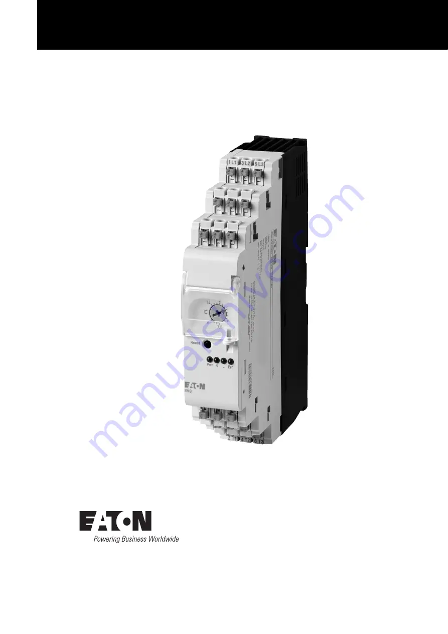
Страница 11: ...ngsspannung 1L1 3L2 5L3 b Ger tefu mit Aufnahme f r Tragschiene c LEDs PWR Versorgungsspannung ERR Meldung Fehler L Linkslauf R Rechtslauf ON Motorstart EMS D d 3 Phasen Ausgangsspannung 2T1 4T2 6T3 e...
Страница 12: ...drehrichtung Die Ansteuerung erfolgt mit 24 V DC ber die Anschlussklemme E Enable erfolgt die Freigabe des Schaltbefehls f r die Motordrehrichtung Zur Freigabe des Schaltbefehls muss dieser Anschluss...
Страница 13: ...ichnung des EMS zu achten 1 5 4 Absicherung Die Absicherung eines 3 Phasen Netzes gegen ber Kurzschluss kann auf die folgenden Arten geschehen Tabelle 2 Absicherung f r IEC Anwendung Tabelle 3 Absiche...
Страница 14: ...m sicheren abgeschalteten Zustand Zum Verlassen dieses Zustandes ist eine Fehlerquittierung notwendig Kapitel 4 Ger testatus und Fehlererken nung Seite 20 Der Links bzw Rechtslauf des Antriebs wird du...
Страница 15: ...einen Fehler erkennt wird das R ck melderelais angesteuert d h der Schlie erkontakt Kontakt 95 98 wird geschlossen bzw der ffner 95 96 ge ffnet Dieses Verhalten entspricht dem eines Motorschutzschalt...
Страница 16: ...Wendestarter 2 1 1 Haupt und Steuerstrompfad beim Direktstarter EMS DO 24VDC Abbildung 2 Direktstarter K1 EMS DO 24VDC T1 Rechtslauf 2 1 2 Haupt und Steuerstrompfad f r Wendestarter EMS RO 24VDC Abbi...
Страница 17: ...rters nur einka nalig abgeschaltet wird ist diese Art der Installation nach SIL 3 Kat 3 Kat 4 nur zul ssig wenn ein Fehlerausschluss f r Querschluss erlaubt ist Dies ist beispielsweise der Fall wenn d...
Страница 18: ...Lebensdauer Abbildung 4 Haupt und Steuerstrompfad NOT HALT einkanalig verringerte Lebensdauer S2 NOT HALT S3 Reset NOT HALT einkanalig nach Kat 3 SIL 3 PL e EMS ROS mit ber geordneter Sicherheitsrelai...
Страница 19: ...aler Betriebs zustand ist wie beispielsweise bei Schutzt r oder Zweihand Applikationen muss eine Schaltung nach Abschnitt 2 3 1 Haupt und Steuerstrompfad NOT HALT einkanalig und Abschnitt 2 3 2 Haupt...
Страница 20: ...HALT einkanalig Abbildung 6 Haupt und Steuerstrompfad NOT HALT einkanalig S2 NOT HALT S3 Reset NOT HALT Applikation einkanalig nach Kat 3 SIL 3 PL e EMS ROS mit bergeordneter Sicherheitsrelais Kombin...
Страница 21: ...T zweikanalig Abbildung 7 Haupt und Steuerstrompfad NOT HALT zweikanalig S2 NOT HALT S3 Reset NOT HALT Applikation zweikanalig nach Kat 3 SIL 3 PL e EMS ROS mit bergeordneter Sicherheitsrelais Kombina...
Страница 22: ...he Motorstarter ist nach dem LED Test bereit f r eine Einstellung des Nennstroms Hierf r ist erforderlich dass kein Fehler beim Ger t vorliegt Die LED ERR ist aus 3 1 Nennstromeinstellung Stellen Sie...
Страница 23: ...rden Eine 230 V AC Bremse ist am Anschluss 4 T2 und dem Sternpunkt des Motors anzuschlie en Die Ansteuerung von externen Bremsen erfolgt ber separate Hilfssch tze z B DILA LED Code Nennstrom mA PWR R...
Страница 24: ...der Peripherie zu erkennen Bei einem erkannten Fehler befindet sich das Ger t im sicheren abgeschalte ten Zustand Alle internen Fehler sind nicht quittierbar sie werden im Ger t gespeichert Das Ger t...
Страница 25: ...kslauf aufgetreten ein aus blinkend blinkend manuell Ein Fehler ist beim Rechtslauf aufgetreten ein blinkend aus blinkend manuell Fehler beim Herstellen des Systemzu standes Checksumme fehlerhaft Das...
Страница 26: ...ers Schlie ers zwischen den Klemmen MAN und RES bzw A1 24VDC und RES realisiert werden Eine Quittierung wird ausgel st sobald am Eingang MAN eine positive Flanke erkannt wird Wird nach Ablauf einer Ze...
Страница 27: ...r glichkeit EMV Elektrostatische Entladung IEC EN 61000 4 2 Luftentladung kV 8 8 Kontaktentladung kV 6 6 Elektromagnetische Felder IEC EN 61000 4 3 80 1000 MHz V m 10 10 1 4 2 GHz V m 10 10 2 2 7 GHz...
Страница 28: ...essungsbetriebsstrom Ie EN 60947 1 AC51 EN60947 4 3 A 0 18 2 4 1 2 9 AC53a EN60947 4 2 A 0 18 2 4 1 2 6 5 Minimale Verlustleistung W 1 1 1 1 Maximale Verlustleistung W 3 3 14 6 Bemessungssto spannungs...
Страница 29: ...chsler Kontaktmaterial Ag Legierung hartvergoldet Ag Legierung hartvergoldet Signalkontakt Leistungskontakt Schaltspannung maximal V 30 AC 36 DC 250 AC DC Schaltspannung minimal 100 mV 12 V AC DC Daue...
Страница 30: ...ebungstemperatur C 40 40 MTTFd a 420 421 Abschaltzeit ms 40 EMS 2 4 80 EMS 9 40 EMS 2 4 80 EMS 9 sd FIT 49 47 su FIT 1818 1582 dd FIT 269 269 du FIT 2 7 2 4 SFF 99 8 99 8 DCS 2 6 2 9 DC 99 99 PFH 1 h...
Страница 31: ...instellung gr er als 4 A 5 4 Deratingkurven bei 100 Einschaltdauer EMS T 9 24VDC Abbildung 10 Deratingkurve bei 100 Einschaltdauer IL Laststrom a Einzelger t b Angereiht mit 30 mm Abstand c Angereiht...
Страница 32: ...otors ermitteln berstromfaktor IA IN 11 2 3 4 5 6 7 82 9 10 Anpassungsfaktor K 1 1 1 1 1 0 96 0 83 0 72 0 64 0 58 1 Gebrauchskategorie AC 51 2 Gebrauchskategorie AC 53a Beispiel 1 Beispiel 2 Motor mit...
Страница 33: ...ird DFFRUGLQJ OLVW RQ SDJH DQG SURYLGHG WKDW LW LV LQVWDOOHG PDLQWDLQHG DQG XVHG LQ DSSOLFDWLRQ LQWHQGHG IRU ZLWK UHVSHFW WR WKH UHOHYDQW PDQXIDFWXUHUV LQVWUXFWLRQV LQVWDOODWLRQ VWDQGDUGV DQG JRRG HQJ...
Страница 34: ...Sortiments 7 SHV ZLWKLQ WKH UDQJH Die Konformit tserkl rung gilt f r folgende Typen der Produktfamilie und in Kombination mit den darunter folgenden Produkten 7KH GHFODUDWLRQ RI FRQIRUPLW DSSOLHV WR W...
Страница 35: ...8 Feedback output 41 2 Engineering 42 2 1 Sample DOL starter and reversing starter circuits 42 2 1 1 Main and control current paths for EMS DO 24VDC DOL starters 42 2 1 2 Main and control current path...
Страница 36: ...ection 50 4 1 Device status 50 4 2 Error acknowledgment 52 5 Appendix 53 5 1 Technical Data 53 5 2 Technical safety functions 56 5 3 Tripping characteristics at 20 C 57 5 4 Derating curves for 100 dut...
Страница 37: ...visions The following significant amendments have been introduced since previous issues 0 2 Target group This manual is intended for qualified personnel in charge of installing commissioning operating...
Страница 38: ...m 0 3 2 Hazard warnings of personal injury 0 3 3 Tips CAUTION Warns of the possibility of hazardous situations that may possibly cause slight injury WARNING Warns of possibility of hazardous situation...
Страница 39: ...ype e Increased Safety These measures improve the degree of safety and prevent impermissible high temperature and develop ment of sparking and arcing which is usually not found when motors are operate...
Страница 40: ...Device type Function Current Range Supply voltage control voltage EMS DO T 2 4 24VDC DOL starter with motor protection 0 18 2 4 A AC 51 0 18 2 4 A AC 53a 24 V DC EMS DO T 9 24VDC DOL starter with mot...
Страница 41: ...e 1L1 3L2 5L3 b Fixing bracket with mount for mounting rail c LEDs PWR supply voltage ERR message error L counterclockwise R clockwise ON motor start EMS D d 3 phase output voltage 2T1 4T2 6T3 e Feedb...
Страница 42: ...of motor rotation They are actuated with 24 V DC Meanwhile connection terminal E Enable is used to enable the switching command for the direction of motor rotation To enable the switching com mand thi...
Страница 43: ...ctly by referring to the motor starter s terminal designations 1 5 4 Protective element The following fuses can be used to protect a 3 phase supply system against short circuits Table 2 Fuse for IEC a...
Страница 44: ...he device will be in a safe disconnected state To leave this state you will have to acknowledge the fault Chapter 4 Device status and fault detection Page 50 The green ON L and R LEDs are used to indi...
Страница 45: ...motor starter detects a fault the feedback relay will be energized i e the N O contact contact 95 98 will be closed or N C con tact 95 96 will be opened This behavior is the same as that of a motor p...
Страница 46: ...Main and control current paths for EMS DO 24VDC DOL starters Figure 2 DOL starter K1 EMS DO 24VDC T1 Clockwise rotation 2 1 2 Main and control current paths for EMS RO 24VDC reversing starters Figure...
Страница 47: ...ff with a sin gle channel configuration this type of installation is only permissible for SIL 3 cat 3 cat 4 if cross fault fault exclusions are allowed This will be the case for example when the elect...
Страница 48: ...Figure 4 Single channel main and control current path emergency stop reduced lifespan S2 Emergency stop S3 Reset Emergency stop single channel as per cat 3 SIL 3 PL e EMS ROS with higher level safety...
Страница 49: ...rotective door and two hand control applications a circuit like the ones shown in Section 2 3 1 Main and control current path emergency stop single channel and Section 2 3 2 Main and con trol current...
Страница 50: ...Figure 6 Main and control current path emergency stop single channel S2 Emergency stop S3 Reset Emergency stop configuration single channel as per cat 3 SIL 3 PL e EMS ROS with higher level safety rel...
Страница 51: ...gure 7 Main and control current path emergency stop dual channel S2 Emergency stop S3 Reset Emergency stop configuration dual channel as per cat 3 SIL 3 PL e EMS ROS with higher level safety relay com...
Страница 52: ...e ready for you to set the rated operational current To be able to set the rated operational cur rent the device must not be indicating any faults The ERR LED must be off 3 1 Setting the rated operati...
Страница 53: ...d to terminals 2 T1 and 6 T3 A 230 V AC brake must be connected to terminal 4 T2 and to the motor s neutral External brakes are actuated using separate contactor relays e g DILA LED code Rated operati...
Страница 54: ...aults peripheral faults When a fault is detected the device will be in a safe disconnected state Internal faults cannot be acknowledged and will be stored in the device If more than 14 internal faults...
Страница 55: ...or has occurred at anticlockwise oper ation on off flashing flashing manual A fault occurred during anticlockwise rota tion on flashing off flashing manual Error while attempting to determine the syst...
Страница 56: ...emented by con necting a pushbutton N O between the MAN and RES A1 24 V DC and RES terminals An acknowledgment signal will be triggered as soon as a positive edge is detected at the MAN input If a neg...
Страница 57: ...magnetic compatibility EMC Electrostatic discharge IEC EN 61000 4 2 Air discharge kV 8 8 Contact discharge kV 6 6 Electromagnetic fields IEC EN 61000 4 3 80 1000 MHz V m 10 10 1 4 2 GHz V m 10 10 2 2...
Страница 58: ...urrent Ie EN 60947 1 AC51 EN60947 4 3 A 0 18 2 4 1 2 9 AC53a EN60947 4 2 A 0 18 2 4 1 2 6 5 Minimum heat dissipation W 1 1 1 1 Max heat dissipation W 3 3 14 6 Rated impulse withstand voltage Uimp kV 6...
Страница 59: ...changeover contact Contact material Ag alloy hard gold plated Ag alloy hard gold plated Signal contact Power contact Maximum switching voltage V 30 AC 36 DC 250 AC DC Minimum switching voltage 100 mV...
Страница 60: ...re C 40 40 MTTFd a 420 421 Shutdown time ms 40 EMS 2 4 80 EMS 9 40 EMS 2 4 80 EMS 9 sd FIT 49 47 su FIT 1818 1582 dd FIT 269 269 du FIT 2 7 2 4 SFF 99 8 99 8 DCS 2 6 2 9 DC current 99 99 PFH 1 h 2 7 x...
Страница 61: ...t settings greater than 4 A 5 4 Derating curves for 100 duty factor EMS T 9 24VDC Figure 10 Derating curve for 100 duty factor IL load current a Stand alone device b Connected in series with a clearan...
Страница 62: ...nt factor IA IN 11 2 3 4 5 6 7 82 9 10 Adjustment factor K 1 1 1 1 1 0 96 0 83 0 72 0 64 0 58 1 Utilization category AC 51 2 Utilization category AC 53a Example 1 Example 2 Motor with overcurrent fact...
Страница 63: ...det wird DFFRUGLQJ OLVW RQ SDJH DQG SURYLGHG WKDW LW LV LQVWDOOHG PDLQWDLQHG DQG XVHG LQ DSSOLFDWLRQ LQWHQGHG IRU ZLWK UHVSHFW WR WKH UHOHYDQW PDQXIDFWXUHUV LQVWUXFWLRQV LQVWDOODWLRQ VWDQGDUGV DQG JRR...
Страница 64: ...des Sortiments 7 SHV ZLWKLQ WKH UDQJH Die Konformit tserkl rung gilt f r folgende Typen der Produktfamilie und in Kombination mit den darunter folgenden Produkten 7KH GHFODUDWLRQ RI FRQIRUPLW DSSOLHV...