3 Installation
3.6 Electrical Installation
DC1-S…20…, DC1-S…OE1 Variable Frequency Drives
05/21 MN040058EN
www.eaton.com
65
3.6.1 Connection to power section
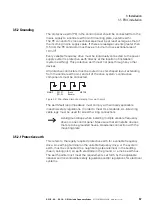
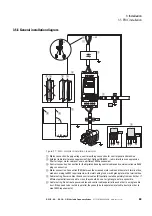
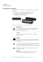
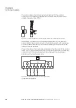
The connection to the power section is normally made via the connection
terminals:
•
L1/L, L2/N, PE for the mains-side supply voltage.
•
U, V, PE for the connection to the motor
•
BR, DC+, PE for an external brake resistor
Figure 38: Connection in power section (schematic)
The number and the arrangement of the connection terminals used depend
on the variable frequency drive’s size and model.
NOTICE
The variable frequency drive must always be connected with
ground potential via a grounding conductor (PE).
L1/L L2/N L3
U
V
W
1
2
3
4
5 6 7 8 9 10 11
Содержание DC1-S1011NB-A20CE1 1
Страница 4: ......
Страница 124: ...5 Operation 5 7 Handling the keypad 120 DC1 S 20 DC1 S OE1 Variable Frequency Drives 05 21 MN040058EN www eaton com...
Страница 160: ...6 Parameter structure 6 7 Fault messages 156 DC1 S 20 DC1 S OE1 Variable Frequency Drives 05 21 MN040058EN www eaton com...
Страница 170: ...7 Technical Data 7 3 Dimensions 166 DC1 S 20 DC1 S OE1 Variable Frequency Drives 05 21 MN040058EN www eaton com...


