


IF 1897 • 10/19 Copyright © 2019, Eaton’s Crouse-Hinds Division Page 3
A
B
165.1
6.50
197.2
7.22-7.89
164.3
6.47
A
B
NOTES:
1. PLACE PARTS IN BAG AND LABEL
HEAT TREATMENT:
REDRAWN DATE
ORIGINAL DATE
UNLESS OTHERWISE SPECIFIED
TOLERANCES
APPROVED BY
MATERIAL:
FINISH:
PATT. I.B.
APPROVED BY
CHECKED BY
DRAWN BY
USED ON
APPLICATION
NEXT ASSY.
DIR NUMBER:
TITLE
CODE IDENT. NO.
SIZE
REV.
CC
HSY
-Templat
e-
D
SW_REV 08/201
3
DO NO
T SCALE DRA
WING
D
1020306691///
07/02/2014
T. DALY
DRT
PSB
PIPE MOUNT KIT, S/A
(PMKIT)
FIRST MADE FOR
MLL
0306691
X1
SCALE 2:1
WT. 0.50 LB
SHEET 1 OF 2
THIS IS PROPERTY OF EATON AND CONTAINS CONFIDENTIAL
AND TRADE SECRET INFORMATION. POSSESSION DOES NOT
CONVEY ANY RIGHTS TO LOAN, SELL OR DISCLOSE SAID
INFORMATION. REPRODUCTION OR USE FOR ANY PURPOSE
OTHER THAN WHICH IT WAS SUPPLIED MAY NOT BE MADE
WITHOUT EXPRESS WRITTEN PERMISSION OF EATON.
THIS DRAWING IS ON LOAN AND IS TO BE
RETURNED UPON REQUEST.
IB
.X
.XX
ANGLES
.XXX
±
± .005
± .01
±
1.5 °
in.
mm
.13
1.5 °
± .3
±
±
±
NOTES:
1.
THIRD ANGLE PROJECTION
A
B
C
D
1
2
3
4
5
6
7
8
A
D
C
B
8
7
6
5
4
3
2
1
UNLESS OTHERWISE SPECIFIED, ALL
PRIMARY DIMENSIONS ARE IN
INCHES. DIMENSIONS IN [ ] ARE IN
MILLIMETERS.
9
10C01-025D20
SCREW, HEX HD, 1/20 x 5/8"
2
8
11A12-025D
WASHER, LOCK, SPRING, 1/4"
2
7
10K01-031D
NUT, HEX, 5/16-18
3
6
11A12-031D
WASHER, LOCK, SPRING, 5/16"
3
5
10C01-031D32
SCREW, HEX HD, 5/16-18 x 1"
2
4
10C01-031D20
SCREW, HEX HD, 5/16-18 x 5/8"
1
3
0306682-2
DURA PRO BACK MOUNT
1
2
0903016
PIPE CLAMP, UPPER
1
1
0903015
PIPE CLAMP, LOWER
1
ITEM
NO.
DWG NUMBER
DESCRIPTION
QTY
CLAMP SIZE
(mm)
MATERIAL
CLAMP,
UPPER PART
NO.
CLAMP,
LOWER PART
NO.
42
SS - 316
CHR5227
CHR5236
SS - 304
CHR5228
CHR5237
STL, ZNC PLTNG
CHR5229
CHR5238
51
SS - 316
CHR5230
CHR5239
SS - 304
CHR5231
CHR5240
STL, ZNC PLTNG
CHR5232
CHR5241
60
SS - 316
CHR5233
CHR5242
SS - 304
CHR5234
CHR5243
STL, ZNC PLTNG
CHR5235
CHR5244
CONFIGURATION
DIMENSION (INCHES)
A
B
C [mm]
D
DIAMETER 60
4.331
3.543
2.36
60
1.693
DIAMETER 51
3.740
2.953
2.01
51
1.535
DIAMETER 42
3.386
2.598
1.65
42
1.378
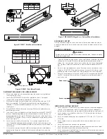
Ø C
A
D
B
Side
Channel
Clamp
1/4 Set Screw
5/16 Screw
Configuration
Dimension (inches)
A
B
C
D
PM Kit 2.0
(trade size 2”)
4.331
3.543
2.36
1.693
PM Kit 1.5
(trade size 1-1/2”)
3.740
2.953
2.00
1.535
PM Kit 1.25
(trade size 1-1/14”)
3.386
2.598
1.65
1.378
Length
(in)
(mm)
A
44.6
1133
B
18-41.6
610-1056
Figure 5. PM KIT - Pole Mount Installation
Figure 6. PM KIT - Pole Mount Details
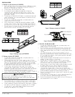
D. MP1054MTK MAGNAPRO OR SURFACE MOUNT
1. Make sure the power is disconnected from the conduit system before
installing the luminaire.
2. Locate the MP1054MTK Kit brackets supplied in the kit. For retrofit,
inspect the existing brackets and replace if necessary.
3. Mark and drill holes to install brackets to wall or ceiling with two (2) 1/4”
bolts (not supplied). For MagnaPro, bracket holes may be spaced as
required, it is recommended to keep them at least 12” (305mm) apart
(see Figure 7).
4. Attach MP1054MTK kit brackets to ceiling. Make sure the brackets are
parallel to each other.
5. Install one (1) channel adapter with slide channel onto each MP1054MTK
bracket. Slide the long edge of the channel adapter into the slots on the
bracket and tighten the two (2) Phillips head screws on the ends of each
MP1054MTK kit bracket. Make sure the slide brackets are parallel to each
other (see Figure 7).
6. Luminaire is now ready for mounting. It is strongly suggested to use
two (2) qualified tradespeople to proceed with the final mounting of the
luminaire. This is recommended to avoid any personal injury or damage to
the luminaire.
7. Lift luminaire into position and slide the luminaire into the slide brackets,
engaging the flange on the top of the luminaire and position it near the
center.
Figure 7. MP1054MTK MagnaPro or Surface Mount Installation
SECONDARY SUPPORT
If using secondary support, attach one end of the support cable to a corner
eyelet provided on the luminaire housing and secure the other end to a fixed
support.
WIRING THE LUMINAIRE
1. Open the threaded wiring access cover (see Figure 8) and allow the cover
to hang by the lanyard. Terminate the equipment grounding conductor
(green) first, the common (white) next, and finally, the line voltage (black)
last. Tighten all electrical connections. Note -Standard openings are 3/4”
NPT.
2. Re-install the threaded access cover. Ensure gasket is seated and clean
of debris. (CAUTION: When replacing cover, make sure that there are no
protruding wires or connectors that would obstruct the status indicator.
3. Refer to wiring diagram in Figure 9 for RV1 or AV1 luminaire and Figure10
for RAV1 luminaire. Maximum four (4) conductors are allowed through
each entry hub.
WARNING
To reduce the risk of ignition of hazardous atmospheres, keep cover tightly
closed during operation.
!
Driver cover
Access cap
Figure 8
WIRING INSTALLATION CHECKLIST
1. Verify sufficient HTL Lubricant is on conduit entries (recommend approx-
imately 1/8” bead around the first thread) and that all unused conduit
entries on the driver cover are closed with lubricated plugs (see Figure 8).
2. Verify conduit is installed for at least five (5) full threads into the driver
cover conduit entries.
3. Verify installed conduit plugs are torqued to 42-52 ft.-lbs. (57-71 N-m) for
3/4” plug.
4. Verify supply wires are connected to luminaire wire leads per wiring
diagrams.
5. Verify all electrical connections are tightened.
6. Verify all wires are safely and neatly inside access cap and not on top of
driver. Re-attach access cap to luminaire housing.
7. Verify access cap is tight and cap is in contact with luminaire housing with
at least five (5) full threads engaged.
327
12.88
241.3
9.50
158.7
6.25
295.4
11.63
A
B
B
A


