Eaton 9SX 15K Series Скачать руководство пользователя страница 14


14 


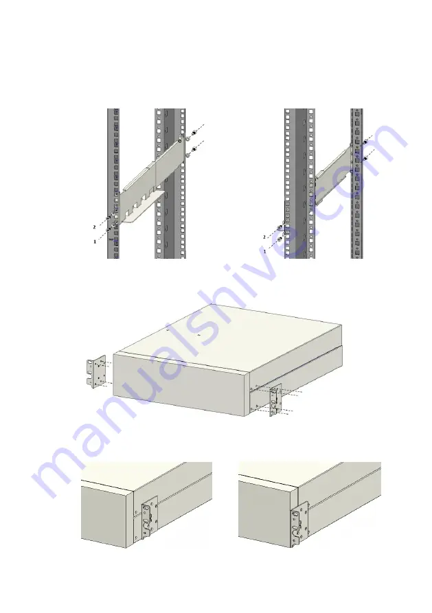
              Fasten the rail kit to cabinet with 8pcs M5  washers (as below): 


2. 

Install the mounting ears. Lock the left/right mounting ears into the MBP with 8pcs of 

M4 flat screws (take note of the correct orientation of the mounting ears as below) 


Note:  There  are  2  other  possible  mounting  positions  for  the  mounting  ears  to  suit 

different rack depths: 


Содержание 9SX 15K Series

Страница 1: ...1 Eaton 9SX 15 20K Series Maintenance ByPass MBP MBP20K MBP20KPDU MBP20KPARA...

Страница 2: ...Copyright 2020 EATON All rights reserved...

Страница 3: ...associated with the risk of electric shock symbol Important instructions that must always be followed The crossed out wheeled bin symbol indicates that electrical and electronic waste should not be d...

Страница 4: ...n and overcurrent protection devices shall be provided by others for permanently connected AC input Normal AC Bypass AC and AC output circuits Check that the indications on the rating plate correspond...

Страница 5: ...rom the carton don t use the straps to carry the unit around The unit may slip from the straps during handling risk of injury and product damage keep 12 30cm minimum distance between the straps lift t...

Страница 6: ...on 13 3 Wiring 16 Cable and connector 18 3 1 Wiring of single MBP Standard version 20 3 2 Wiring of single MBP Basic version 33 3 3 Wiring of 1 1 parallel MBP standard version 35 4 Operation 49 4 1 Wi...

Страница 7: ...ording to an eco design approach Substances This product does not contain CFCs HCFCs or asbestos Packaging To improve waste treatment and facilitate recycling separate the various packaging components...

Страница 8: ...29 3U 465 12 8 single MBP Basic version MBP20KPDU 438 129 3U 465 13 6 single MBP Standard version MBP20KPARA 438 129 3U 465 19 9 1 1 parallel MBP Standard version Notes 1 Total of 4 input output modes...

Страница 9: ...9 1 2 Appearance Front view With front panel Notes 1 Ventilation area 2 Maintenance Bypass label 1 2 1 Single MBP Basic version Front view Remove front panel Rear view...

Страница 10: ...enance bypass switch 1 2 2 Single MBP standard version Front view Remove front panel Rear view Note 1 RJ45 ports Detect EBM MBP 2 AC input terminal ports 3 AC output segment 1 Not programmable 4 AC ou...

Страница 11: ...1 2 3 1 1 parallel MBP standard version Front view Remove front panel Rear view Note 1 RJ45 ports Detect EBM MBP 2 AC input terminal ports 3 AC output segment 1 Not programmable 4 AC output segment 2...

Страница 12: ...ier immediately Do not carry the modules by the front and rear panels 2 1 1 Unpacking the Unit 2 1 2 Inspecting accessories MBP accessories MBP20K MBP20KPDU MBP20KPARA MBP detection cable Cable to UPS...

Страница 13: ...allation Allow for 500mm front and rear clearance from the module for ventilation Do not carry the front rear panel of the module during installing 2 2 1 Rack mount The Installation steps are the same...

Страница 14: ...Install the mounting ears Lock the left right mounting ears into the MBP with 8pcs of M4 flat screws take note of the correct orientation of the mounting ears as below Note There are 2 other possible...

Страница 15: ...ers as below 2 2 2 Tower mount 1 Place the MBP on the left side of the UPS and align it with the front panel of the UPS module 2 Position the pedestal feet that is included as part of the UPS power mo...

Страница 16: ...ous voltages on all terminals The rated current requirement of the feeder protection contactor is greater than the rated current of the MBP Wiring diagram as shown below Before any connections ensure...

Страница 17: ...D type 40A 40A MBP20KPARA 1 phase main input D type 230A 230A 3 phase main input D type 80A 80A 1 phase bypass input D type 160A 160A 3 phase bypass input D type 63A 63A 1 phase output D type 160A 160...

Страница 18: ...wo tables for the cross sectional dimensions in mm Each for 15kvA and 20kVA UPS respectively 15kVA UPS MBP Model Input Output Mode Input Output Main input Bypass input Ground wire L wire N wire L wire...

Страница 19: ...Bypass input Ground wire L wire N wire L wire N wire L wire N wire Ground wire MBP20K MBP20KPDU 3 1 10 10 25 25 25 25 25 25 3 3 10 10 10 10 10 10 10 10 1 1 50 50 25 25 50 25 25 25 1 3 50 50 10 10 50 1...

Страница 20: ...e N N L1 L2 L3 PE 4 UPS input TB PE N N L1 L2 L3 5 UPS bypass TB L1 L2 L3 6 UPS output TB N N L1 L2 L3 This section outlines the 8 different possible modes of input output wiring applications Below is...

Страница 21: ...as 4 pieces of Mode setting label are included as accessories 3 3 single source 3 3 dual source 3 1 single source 3 1 dual source 2 To configure to the following 4 modes of connection contact your sup...

Страница 22: ...put terminal mL1 bL1 bL2 bL3 with busbar 4 then connect the AC cable L1 to it IV Connect the AC input terminal mL2 mL3 to the AC cable L2 L3 2 Output I Connect the main ground cable PE to the chassis...

Страница 23: ...Connect the AC main source cable N and bypass source cable N with lugs on top of each other to the aforementioned N N terminal busbar 1 IV Connect the AC input terminals mL1 mL2 mL3 to main source ca...

Страница 24: ...e UPS II Connect the UPS to MBP with the Cable to UPS1 included in the MBP s accessory 3 1 3 Mode 3 3 single source 1 Input I Connect the main ground cable PE to the chassis II Bridge the AC input ter...

Страница 25: ...Output I Connect the ground cable PE to the chassis II Bridge the AC segment terminal N N with busbar 1 then connect the AC cable N to it III Connect the AC segment terminals L1 L2 L3 to the AC cable...

Страница 26: ...mL1 mL2 mL3 to the main source cables L1 L2 L3 V Connectthe AC input terminals bL1 bL2 bL3 to bypass source cables L1 L2 L3 2 Output I Connect the ground cable PE to the chassis II Bridge the AC segme...

Страница 27: ...he AC input terminals mL1 bL1 mL2 bL2 mL3 bL3 with busbar 6 then connect the AC cable L to it 2 Output I Connect the ground cable PE to the chassis II Bridge the AC segment terminal N N with busbar 1...

Страница 28: ...l N N with busbar 1 III Connect the AC main source cable N and bypass source cable N with lugs on top of each other to the aforementioned N N busbar 1 IV Bridge the AC input terminals mL1 mL2 mL3 with...

Страница 29: ...le N to it III Bridge the AC segment terminals L1 L2 L3 with busbar 3 then connect the AC cable L to it 3 Connection to the UPS I Remove all the busbars of the UPS II Connect the UPS to the MBP with t...

Страница 30: ...e L to it 2 Output I Connect the ground cable PE to the chassis II Bridge the AC segment terminal N N with busbar 1 then connect the AC cable N to it III Connect the AC segment terminals L1 L2 L3 to t...

Страница 31: ...able N with lugs on top of each other to the aforementioned N N terminal busbar 1 IV Bridge the AC input terminals mL1 mL2 mL3 with busbar 5 then connect the main source cable L to it 2 Output I Conne...

Страница 32: ...PS1 included in the MBP s accessory Notes Bypass is not available in this mode Please use with caution Single MBP standard verson includes IEC output sockets It is recommended to install the Cable Loc...

Страница 33: ...put TB PE N N L1 L2 L3 4 UPS bypass TB L1 L2 L3 5 UPS output TB N N L1 L2 L3 As like the MBP standard version the MBP Basic version also provides 8 possible modes of wiring applications Please select...

Страница 34: ...3 1 single source 3 1 dual source 2 To configure to the following 4 modes of connection contact your supplier for the issue of Copper Busbars 6 7 and 8 as well as the corresponding Mode setting label...

Страница 35: ...L1 L2 L3 3 AC segment 2 Programmable N N N L1 L2 L3 PE 4 UPS1 TB ports 5 UPS2 TB ports This section outlines the 8 different possible modes of input output wiring applications Below is a list of coppe...

Страница 36: ...as well as 4 pcs of Mode setting label are included as accessories 3 3 single source 3 3 dual source 3 1 single source 3 1 dual source 2 To configure to the following 4 modes of connection contact yo...

Страница 37: ...sis II Bridge the AC input terminal N N N with busbar 9 then connect the AC source cable N to it III Bridge the AC input terminals mL1 bL1 bL2 bL3 with busbar 15 then connect the AC cable L1 to it IV...

Страница 38: ...II Bridge the AC segment terminals L1 L2 L3 with busbar 3 then connect the AC cable L to it 3 Connecting to UPS 1 and UPS 2 I Remove all busbars of the UPS II Connect UPS 1 and UPS 2 to the MBP with C...

Страница 39: ...ridge the AC input terminal bL1 bL2 bL3 with busbar 12 then connect the bypass source cable L to it 2 Output I Connect the ground cable PE to the chassis II Bridge the AC segment terminal N N N with b...

Страница 40: ...rminal N N N with busbar 9 then connect the AC cable N to it III Bridge the AC input terminal mL1 bL1 with busbar 10 then connect the AC cable L1 to it IV Bridge the AC input terminal mL2 bL2 with bus...

Страница 41: ...th busbar 3 then connect the AC cable N to it III Connect the AC segment terminal L1 L2 L3 to AC cable L1 L2 L3 3 Connecting to UPS 1 and UPS 2 III Remove all busbars of the UPS IV Connect UPS 1 and U...

Страница 42: ...onnect the AC input terminal bL1 bL2 bL3 to the bypass source cable L1 L2 L3 2 Output I Connect the ground cable PE to the chassis II Bridge the AC segment terminal N N N with busbar 3 then connect th...

Страница 43: ...nnect the AC cable N to it III Bridge the AC input terminal mL1 bL1 mL2 bL2 mL3 bL3 with busbar 11 then connect the AC cable L to it 2 Output I Connect the ground cable PE to the chassis II Bridge the...

Страница 44: ...and UPS 2 to the MBP with Cable to UPS 1 and Cable to UPS 2 included in the MBP s accessory 3 3 6 Mode 1 1 Dual source 1 Input I Connect the main ground cable PE to the chassis II Bridge the AC input...

Страница 45: ...t 2 Output I Connect the ground cable PE to the chassis II Bridge the AC segment terminal N N N with busbar 3 then connect the AC cable N to it III Bridge the AC segment terminal L1 L2 L3 with busbar...

Страница 46: ...nput terminal N N N with busbar 9 then connect the AC cable N to it III Bridge the AC input terminal mL1 bL1 mL2 mL3 with busbar 14 then connect the AC cable L to it 2 Output I Connect the ground cabl...

Страница 47: ...3 3 Connecting to UPS 1 and UPS 2 I Remove all busbars of the UPS II Connect UPS 1 and UPS 2 to the MBP with Cable to UPS 1 and Cable to UPS 2 included in the MBP s accessory Note Bypass is not availa...

Страница 48: ...e AC input terminal bL1 to the bypass source cable L 2 Output I Connect the ground cable PE to the chassis II Bridge the AC segment terminal N N N with busbar 3 then connect the AC cable N to it III C...

Страница 49: ...ection of the parallel cable between multiple UPS Set up the system s detection loop following the steps below 1 MBP detection connect the MBP to UPS1 via the MBP Detection cable included with the MBP...

Страница 50: ...50...

Страница 51: ...PS will transfer to internal bypass automatically given MBP detection cables are connected properly 3 Rotate the handle of the Maintenance Bypass Switch to the MAINTENANCE position Open the Input swit...

Страница 52: ...for maintenance replacement Caution When removing the UPS to MBP connection cables only remove the top cover of the terminal box Leave the AC input output connection terminal box as is to prevent ele...

Страница 53: ...53 Appendix 1 System block diagram...

Страница 54: ...AX Rated current Three phase input 43A MAX 86A MAX Bypass Rated voltage Phase voltage 220 230 240VAC Frequency 50 60Hz Rated current Single phase input 93A MAX 186A MAX Rated current Three phase input...

Страница 55: ......

Страница 56: ...614 40048 00...

Отзывы: