76
Eaton 93PM-L 20–200kW (208V) UPS Installation and Operation Manual 164000724—Rev 01
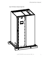
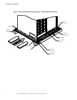
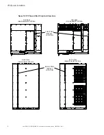
30. Using the retained cabinet mounting bolts, install the floor mounting brackets to the left and right side of
the UPS with the angle facing outward.
31. Secure the cabinet to the floor with customer-supplied hardware.
32. Proceed to paragraph
Integrated Battery Cabinet Installation
.
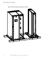
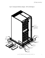
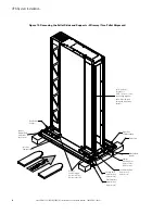
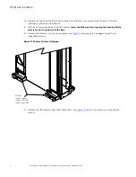
33. Locate the front and back floor mounting brackets from the floor mounting kit.
34. Using the retained cabinet mounting bolts, install the floor mounting brackets to the front and rear of the
UPS with the angle facing outward.
35. Secure the cabinet to the floor with customer-supplied hardware.
NOTE
Black cover dots are provided, if side mounting bracket holes need to be covered for
aesthetic reasons.
36. Locate the black cover dots from the parts kit and install over the left and right side bracket mounting
holes.
37. Proceed to paragraph
Integrated Battery Cabinet Installation
.
44..33
IInntteeggrraatteedd B
Baatttteerryy C
Caabbiinneett IInnssttaallllaattiioonn
If installing Integrated Battery Cabinets (IBCs), refer to the
Eaton 93PM Universal Integrated Battery Cabinet
Installation Manual-Large and Large High Rate
, or the
Eaton 93PM Integrated Battery Cabinet-Small Welded
IBC-SW (432V and 480V) Installation Manual
, listed in paragraph 1.8, for installation instructions.
44..44
EExxtteerrnnaall A
AC
C P
Poow
weerr W
Wiirriinngg IInnssttaallllaattiioonn
To install wiring:
1.
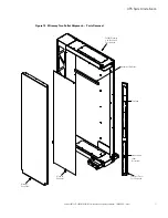
Remove the screws securing the Wireway Hang Panel and remove the panel. Retain the hardware for later
use.
2.
Remove the screws securing the internal safety shield (deadfront) panel and remove the panel to gain
access to the input, output, and battery power wiring terminals. Retain the hardware for later use.
3.
Bottom Entry Wiring.
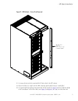
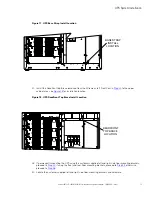
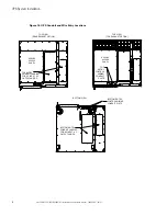
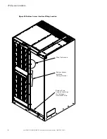
Remove the bottom conduit plate (see
) from the bottom of the UPS.
Identify all conduit requirements and mark their location. Drill and punch all conduit holes in the bottom
conduit plate prior to mounting on the UPS. Install the conduit plate and install all conduit runs into the
plate. Pull the wiring through conduit into the wiring area.
4.
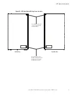
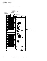
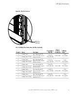
Route the input and output cables through the bottom of the cabinet to the UPS terminals. See
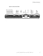
for wiring access information, and
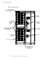
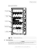
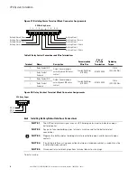
for terminal locations.
5.
Proceed to
6.
Top Entry Wiring.
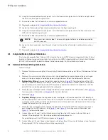
Remove the top conduit plate (see Figure 4–5) from the top of the UPS. Identify all
conduit requirements and mark their location. Drill and punch all conduit holes in the top conduit plate prior
to mounting on the UPS. Install the conduit plate and install all conduit runs into the plate. Pull the wiring
through the conduit into the wiring area.
7.
Route the input and output cables through the top of the UPS and the UPS inter-cabinet wiring access
pass-through to the UPS terminals. See
and
for wiring access information, and
for terminal locations.
8.
Connect phase A, B, and C rectifier input power wiring from the utility source to the rectifier input
terminals. See paragraph 3.2.2 for wiring and termination requirements.
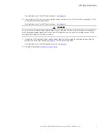
For a detailed view of the UPS terminal blocks, see
9.
Connect phase A, B, and C bypass input power wiring from the utility source to the bypass input terminals.
See paragraph 3.2.2 for wiring and termination requirements.
Содержание 93PM-L IAC-B
Страница 1: ...p n 164000724 Revision 01 20 200 kW 208V UPS Installation and Operation Manual Eaton 93PM L UPS ...
Страница 10: ...x Eaton 93PM L 20 200kW 208V UPS Installation and Operation Manual 164000724 Rev 01 List of Tables ...
Страница 112: ...102 Eaton 93PM L 20 200kW 208V UPS Installation and Operation Manual 164000724 Rev 01 UPS System Installation ...
Страница 148: ...138 Eaton 93PM L 20 200kW 208V UPS Installation and Operation Manual 164000724 Rev 01 Communication ...
Страница 154: ...144 Eaton 93PM L 20 200kW 208V UPS Installation and Operation Manual 164000724 Rev 01 UPS Maintenance ...
Страница 158: ...148 Eaton 93PM L 20 200kW 208V UPS Installation and Operation Manual 164000724 Rev 01 Product Specifications ...
Страница 161: ...Eaton 93PM L 20 200kW 208V UPS Installation and Operation Manual 164000724 Rev 01 151 Warranty ...
Страница 162: ...16400072401 164000724 01 ...

