


Eaton 93PM-L 20–200kW (208V) UPS Installation and Operation Manual 164000724—Rev 01
135
C
Chhaapptteerr 77 C
Coom
mm
muunniiccaattiioonn
This chapter describes the communication features of the Eaton 93PM-L UPS. For terminal wiring information,
see paragraph
UPS System Interface Wiring Preparation
and paragraph
Installing Interface Connections
. For location of the customer interface panel and terminals, see
and
77..11
M
Miinniisslloott C
Caarrddss
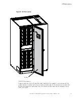
The Eaton 93PM-L UPS has four standard, factory-installed Minislot communication bays. See
for bay
locations. The UPS is compatible with the following Minislot cards (see
•
The Power Xpert Gateway Minislot (PXGMS) card provides Web-enabled, real-time monitoring of Eaton
93PM uninterruptible power systems (UPSs) through standard Web pages, Power Xpert software,
Intelligent Power Manager (IPM), Intelligent Power Protector (IPP), or third-party software. As an integral
part of the Eaton Power Xpert Architecture
®
, the PXGMS card provides a central point to connect UPSs to
the Ethernet network.
Network managers can view critical downstream device information, such as status, power, energy, and
power quality data with an easy-to-use interface.
•
Industrial Relay Card-Minislot (IRC-MS) – can be used to indicate the operating status of the UPS system
using the customer's monitoring equipment. The Industrial Relay Card uses five isolated normally-open or
normally-closed dry relay contacts to indicate the UPS status. Normal, Bypass, Battery, and Alarm modes
can be monitored. See
for default triggers. The contact ratings and wire range are listed in the
IRC-MS installation guide. One input can be activated by a switch or dry contact. The voltage source is
provided by the card, no external voltage source is needed.
For installation and setup of a Minislot card, contact an Eaton service representative (see paragraph
). Refer to the manual supplied with the Minislot card for user instructions.
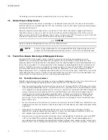
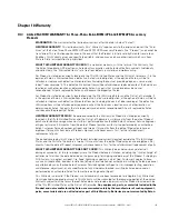
Figure 62. Optional Minislot Cards
Ident
Power
Act
100
PXGMS UPS
Restart
TX
RX
Setup
CMN
Status
DHCP
EMP
Ethernet 10/100
+
-
Table 34. IRC-MS Default Triggers
Relay
Trigger
K1
UPS supporting the load
K2
UPS on Battery
K3
Summary alarm
K4
UPS on bypass
K5
UPS battery low
77..22
B
Buuiillddiinngg A
Allaarrm
m M
Moonniittoorriinngg
This standard feature lets you connect the UPS to your building alarms, such as smoke detectors or
overtemperature alarms. The building alarm customer interface terminals for external are located inside the
UPS. Use twisted-pair wires for each alarm input and common.
Содержание 93PM-L IAC-B
Страница 1: ...p n 164000724 Revision 01 20 200 kW 208V UPS Installation and Operation Manual Eaton 93PM L UPS ...
Страница 10: ...x Eaton 93PM L 20 200kW 208V UPS Installation and Operation Manual 164000724 Rev 01 List of Tables ...
Страница 112: ...102 Eaton 93PM L 20 200kW 208V UPS Installation and Operation Manual 164000724 Rev 01 UPS System Installation ...
Страница 148: ...138 Eaton 93PM L 20 200kW 208V UPS Installation and Operation Manual 164000724 Rev 01 Communication ...
Страница 154: ...144 Eaton 93PM L 20 200kW 208V UPS Installation and Operation Manual 164000724 Rev 01 UPS Maintenance ...
Страница 158: ...148 Eaton 93PM L 20 200kW 208V UPS Installation and Operation Manual 164000724 Rev 01 Product Specifications ...
Страница 161: ...Eaton 93PM L 20 200kW 208V UPS Installation and Operation Manual 164000724 Rev 01 151 Warranty ...
Страница 162: ...16400072401 164000724 01 ...


