39
UPS 20-30 kVA, 230 V 0/60 Hz output
User’s Guide
1026743
Revision B
10. Parallel systems
Overview
Parallel UPS configurations are recognised as either redundancy or capacity systems. The
redundancy system is used to improve the system reliability with N+1 redundant UPS module.
The capacity system for its part provides the maximum output power without focusing to the
highest system reliability.
A parameter selection is used to switch between the redundancy and capacity modes. It is
important to remember that the mode is affecting to the output power rating and overall system
reliability.
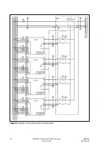
UPS modules of the parallel system share equally the load with Hot Sync™ technology. The
parallel outputs can be combined in a System Parallel Module or cabinet. It is the system
component containing the obligatory service switches. Customer’s low-voltage distribution
panel can also be used instead of the System Parallel Module. In the redundancy system,
service switches enable the maintenance or service on an UPS module. In the capacity system,
one needs to have a common system bypass switch to do the maintenance or service without
safety hazards.
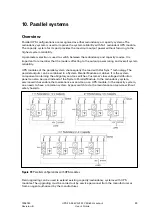
Figure 19
Parallel configurations with UPS modules.
Field upgrading can be used to extend existing capacity/redundancy systems with UPS
modules. The upgrading must be carried out by service personnel from the manufacturer or
from an agent authorised by the manufacturer.

