background image

72

Eaton 9155 UPS (8–15 kVA) User’s Guide 164201553—Rev H0

1.

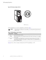
If you have an optional MBM/PDM, verify that the maintenance bypass switch is in the UPS position (see

Figure 52

).

2.

Switch all battery circuit breakers to the ON position.

NOTE

Leave the battery circuit breaker(s) in the ON position during this operation. If you need
to cancel this operation, wait until the front panel LCD illuminates before switching the
battery circuit breaker(s) off.

3.

Wait for the front panel LCD to illuminate.

4.

Press any button on the front panel display to activate the menu options.

5.

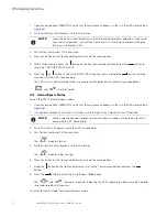
Within three minutes, press the

button on the front panel display and then press the

button to

select the TURN UPS ON/OFF menu.

6.

Press the

or

button to select the TURN UPS ON option; press and hold the

button for three

seconds, until the UPS stops beeping.

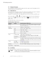
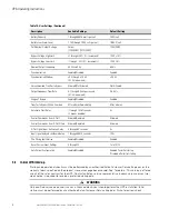
The UPS starts in Battery mode within two minutes and supplies battery power to your equipment.

and

are illuminated.

77..22..33

IInntteerrnnaall B

Byyppaassss S

Sttaarrttuupp

To start the UPS in internal Bypass mode:

1.

If you have an optional MBM/PDM, verify that the maintenance bypass switch is in the UPS position (see

Figure 52

).

2.

If an optional isolation transformer is installed, switch the input circuit breaker to the ON position.

NOTE

When using the optional isolation transformer, Bypass mode is available only for 240V
phase-phase (180° phase angle).

3.

Switch ON the utility power where the UPS is connected.

4.

Wait for the front panel LCD to illuminate.

The

indicator flashes.

5.

Switch all battery circuit breakers to the ON position.

The

indicator stops flashing.

6.

Press any button on the front panel display to activate the menu options.

7.

Using the

button on the front panel display, scroll to the Control menu option and press the

button.

8.

Press the

button to select the Go to Bypass Mode option.

The

and

indicators illuminate, indicating the UPS is operating in Bypass mode. The load

is now powered by utility power.

To switch to Normal mode from internal Bypass mode:

UPS Operating Instructions

Содержание 9155 UPS

Страница 1: ...p n 164201553 Revision H0 8 15 kVA User s Guide Eaton 9155 UPS ...

Страница 2: ...uant to part 15 of the FCC Rules These limits are designed to provide reasonable protection against harmful interference when the equipment is operated in a commercial environment This equipment generates uses and can radiate radio frequency energy and if not installed and used in accordance with the instruction manual may cause harmful interference to radio communications Operation of this equipm...

Страница 3: ...TRUCCIONES DE SEGURIDAD IMPORTANTES GUARDE ESTAS INSTRUCCIONES 9 3 3 U UP PS S I In ns st ta alllla at tiio on n P Plla an n a an nd d U Un np pa ac ck kiin ng g 1 11 1 3 1 Creating an Installation Plan 11 3 2 Preparing the Site 11 3 2 1 Environmental and Installation Considerations 11 3 3 UPS System Power Wiring Preparation 23 3 4 Inspecting and Unpacking the Equipment 26 4 4 U UP PS S S Sy ys st...

Страница 4: ...nging the Language 68 7 1 2 Display Functions 68 7 1 3 User Settings 68 7 2 Initial UPS Startup 70 7 2 1 Normal Mode Startup 71 7 2 2 Starting the UPS on Battery 71 7 2 3 Internal Bypass Startup 72 7 2 4 Maintenance Bypass Startup 73 7 3 UPS Shutdown 73 7 4 UPS Bypass Operation 73 7 4 1 Transfer the load from the UPS to maintenance bypass 75 7 4 2 Transfer the load from maintenance bypass to the U...

Страница 5: ...0 Figure 15 Removing the Pallet 30 Figure 16 UPS Rear View 32 Figure 17 UPS Terminal Block 33 Figure 18 UPS with Input Isolation Transformer Rear View 34 Figure 19 Input Isolation Transformer Hardwiring 35 Figure 20 UPS Rear View 2 High Cabinet Shown 36 Figure 21 Attaching the L Brackets 37 Figure 22 Installing the MBM or PDM 37 Figure 23 Securing the MBM or PDM 38 Figure 24 UPS with MBM Rear View...

Страница 6: ...Terminals 59 Figure 44 Removing the Front Covers 60 Figure 45 Installing Communication Cables 60 Figure 46 Removing Knockout Tabs 61 Figure 47 Reinstalling the Front Covers 61 Figure 48 Communication Port 62 Figure 49 Optional X Slot Cards 63 Figure 50 External Control Terminal Connections 64 Figure 51 Eaton 9155 Control Panel 67 Figure 52 Maintenance Bypass Switch 74 Figure 53 Typical Hardwired I...

Страница 7: ...Table 6 MBM PDM Terminal Block TB10 Wiring 25 Table 7 Communication Port Pin Assignment 62 Table 8 Programmable Signal Inputs 66 Table 9 Menu Map for Display Functions 68 Table 10 User Settings 69 Table 11 UPS Mounted Bypass Switch Positions 74 Table 12 Troubleshooting Guide 81 Table 13 Model List 83 Table 14 Dimensions and Weights 83 Table 15 Environmental and Safety Specifications 84 Table 16 Te...

Страница 8: ...viii Eaton 9155 UPS 8 15 kVA User s Guide 164201553 Rev H0 List of Tables ...

Страница 9: ... you can safely eliminate the effects of electrical line disturbances and guard the integrity of your systems and equipment Figure 1 shows the Eaton 9155 UPS and an optional Extended Battery Module EBM Figure 1 The Eaton 9155 UPS and EBM 2 High Cabinets Shown Eaton 9155 EBM UPS Providing outstanding performance and reliability the Eaton 9155 s unique benefits including the following Online UPS des...

Страница 10: ...ing options The BPM provides added reliability to Eaton uninterruptable power supply UPS systems by ensuring seamless uninterrupted no break transfer as well as a lock out tag out LOTO feature to ensure the greatest safety for UPS technicians and electricians The BPM also offers output distribution in order to simplify wiring in a rackmount IT environment potentially removing the need for a panelb...

Страница 11: ... nt tiio on ns s U Us se ed d iin n T Th hiis s M Ma an nu ua all This manual uses these type conventions Bold type highlights important concepts in discussions key terms in procedures and menu options or represents a command or option that you type or enter at a prompt Italic type highlights notes and new terms where they are defined Screen type represents information that appears on the screen o...

Страница 12: ... or r M Mo or re e I In nf fo or rm ma at tiio on n Refer to the Eaton 9155 Parallel UPS 8 15 kVA User s Guide for the following additional information Installation instructions including site preparation planning for installation wiring and safety information and detailed illustrations of cabinets with dimensional and connection point drawings Operation including breakers standard features and op...

Страница 13: ...her countries Call your local service representative Please have the following information ready when you call for service Model number Serial number Firmware version number Date of failure or problem Symptoms of failure or problem Customer return address and contact information Please use the following e mail address for manual comments suggestions or to report an error in this manual E ESSDocume...

Страница 14: ...6 Eaton 9155 UPS 8 15 kVA User s Guide 164201553 Rev H0 Introduction ...

Страница 15: ...r electric shock install this UPS in a temperature and humidity controlled indoor environment free of conductive contaminants Ambient temperature must not exceed 40 C 104 F Do not operate near water or excessive humidity 95 maximum To reduce the risk of fire connect only to a circuit provided with 100 amperes maximum branch circuit overcurrent protection in accordance with the National Electrical ...

Страница 16: ...tteries Les prises de sortie peuvent être sous tension même lorsque l onduleur n est pas branché sur le secteur Pour réduire les risques d incendie et de décharge électrique installer l onduleur uniquement à l intérieur dans un lieu dépourvu de matériaux conducteurs où la température et l humidité ambiantes sont contrôlées La température ambiante ne doit pas dépasser 40 C Ne pas utiliser à proximi...

Страница 17: ...baterías Los receptáculos de salida pueden transmitir corriente eléctrica aun cuando el SIE no esté conectado a un suministro de corriente alterna c a Para reducir el riesgo de incendio o de choque eléctrico instale este SIE en un lugar cubierto con temperatura y humedad controladas libre de contaminantes conductores La temperatura ambiente no debe exceder los 40 C No trabaje cerca del agua o con ...

Страница 18: ...10 Eaton 9155 UPS 8 15 kVA User s Guide 164201553 Rev H0 Safety Warnings ...

Страница 19: ...ecified 3 3 2 2 1 1 E En nv viir ro on nm me en nt ta all a an nd d I In ns st ta alllla at tiio on n C Co on ns siid de er ra at tiio on ns s The UPS system installation must meet the following guidelines The system must be installed on a level floor suitable for computer or electronic equipment The system must be operated at an altitude no higher than 1500m 5000 ft without derating For additiona...

Страница 20: ...irements for operation of the UPS are Ambient Temperature Range 5 40 C 41 104 F Recommended Operating Range 5 40 C 41 104 F Maximum Relative Humidity 5 95 noncondensing CAUTION If battery systems are located in the same room as the UPS the battery manufacturer s environmental requirements should be followed if they are more stringent than the UPS requirements Operating temperatures above the recom...

Страница 21: ...Isolation Transformer 558 140 263 2 High EBM 480 120 226 3 High EBM 710 178 335 The UPS cabinet uses forced air cooling to regulate internal component temperature Allow clearance in front of and in back of the cabinet for proper air circulation The clearances required around the UPS cabinet are shown in the following table Table 3 UPS Cabinet Clearances From Front of Cabinet 36 91 4 cm working spa...

Страница 22: ...14 Eaton 9155 UPS 8 15 kVA User s Guide 164201553 Rev H0 Figure 2 UPS Cabinet Dimensions 2 High Front and Right Side Views Dimensions are in millimeters inches UPS Installation Plan and Unpacking ...

Страница 23: ...on 9155 UPS 8 15 kVA User s Guide 164201553 Rev H0 15 Figure 3 Extended Battery Module Dimensions 2 High Front and Right Side Views Dimensions are in millimeters inches UPS Installation Plan and Unpacking ...

Страница 24: ...16 Eaton 9155 UPS 8 15 kVA User s Guide 164201553 Rev H0 Figure 4 UPS Cabinet Dimensions 3 High Front and Right Side Views Dimensions are in millimeters inches UPS Installation Plan and Unpacking ...

Страница 25: ...on 9155 UPS 8 15 kVA User s Guide 164201553 Rev H0 17 Figure 5 Extended Battery Module Dimensions 3 High Front and Right Side Views Dimensions are in millimeters inches UPS Installation Plan and Unpacking ...

Страница 26: ...18 Eaton 9155 UPS 8 15 kVA User s Guide 164201553 Rev H0 Figure 6 UPS Cabinet Dimensions 2 or 3 High Top and Bottom Views Dimensions are in millimeters inches UPS Installation Plan and Unpacking ...

Страница 27: ...ton 9155 UPS 8 15 kVA User s Guide 164201553 Rev H0 19 Figure 7 Extended Battery Module Dimensions 2 or 3 High Top and Bottom Views Dimensions are in millimeters inches UPS Installation Plan and Unpacking ...

Страница 28: ...igure 8 2 High UPS Cabinet Center of Gravity Dimensions are in millimeters inches Weight and Center of Gravity Dimensions mm in See Figure 8 Weight kg lb A B C Eaton 9155 8 15 kVA UPS 2 High 81 3 2 452 17 8 406 16 0 169 373 UPS Installation Plan and Unpacking ...

Страница 29: ... 9 2 High EBM Cabinet Center of Gravity Dimensions are in millimeters inches Weight and Center of Gravity Dimensions mm in See Figure 9 Weight kg lb A B C Eaton 9155 Extended Battery Module 2 High 81 3 2 452 17 8 406 16 0 218 480 UPS Installation Plan and Unpacking ...

Страница 30: ...gure 10 3 High UPS Cabinet Center of Gravity Dimensions are in millimeters inches Weight and Center of Gravity Dimensions mm in See Figure 10 Weight kg lb A B C Eaton 9155 8 15 kVA UPS 3 High 81 3 2 452 17 8 610 24 0 276 609 UPS Installation Plan and Unpacking ...

Страница 31: ...of Gravity Dimensions mm in See Figure 11 Weight kg lb A B C Eaton 9155 Extended Battery Module 3 High 81 3 2 452 17 8 610 24 0 276 609 3 3 3 3 U UP PS S S Sy ys st te em m P Po ow we er r W Wiir riin ng g P Pr re ep pa ar ra at tiio on n Read and understand the following notes while planning and performing the installation UPS Installation Plan and Unpacking ...

Страница 32: ... Input neutral must be wired for proper operation Failure to connect an input neutral will void the warranty If the optional input transformer is installed an input neutral is not required The Eaton 9155 UPS is a single feed UPS only Table 4 UPS Terminal Block TB1 Wiring Wire Function Terminal Position Input Circuit Breaker Rating Minimum Wire Size Tightening Torque Conduit Connection Entry Size I...

Страница 33: ...a larger AWG size than shown in this table because of temperature number of conductors in the conduit or long service runs Follow local requirements Table 6 MBM PDM Terminal Block TB10 Wiring Wire Function Input Circuit Breaker Rating Minimum Wire Size Tightening Torque Conduit Connection Entry Size Input Ground 8 AWG 120 lb in 13 5 Nm 2 access hole for 1 1 2 conduit L1 8 kVa 10 kVA 12 kVA 15 kVA ...

Страница 34: ...allet 4 Remove the protective packaging material from the cabinet and recycle in a responsible manner Retain any parts kits packaged with the cabinet 5 Inspect the contents for any evidence of physical damage and compare each item with the Bill of Lading If damage has occurred or shortages are evident contact an Eaton service representative immediately to determine the extent of the damage and its...

Страница 35: ...lt the cabinets more than 10 during installation Remove conduit landing plates to add conduit landing holes as required If perforated floor tiles are required for ventilation place them in front of the UPS 4 4 2 2 U Un nllo oa ad diin ng g t th he e U UP PS S C Ca ab biin ne et t f fr ro om m t th he e P Pa alllle et t The following tools are required for unloading the cabinet s 15 mm wrench or so...

Страница 36: ...for later re assembly onto the cabinet 4 Remove the front cover from the bottom cabinet to access the front shipping bracket Press and release the handle latch at the bottom of the cover and then lift the cover up and off the cabinet 5 Remove the three M10 bolts securing the rear shipping pad to the pallet and remove the shipping pad see Figure 13 NOTE Hold the back of the cabinet so that the bolt...

Страница 37: ... removed in Step 4 Hang the top edge of the cover on the cabinet first then lower the bottom edge and snap into place NOTE Be sure to support the front and back of the cabinet when rolling it off the pallet to prevent tipping 8 Slowly roll the cabinet toward the rear of the pallet Once the pallet tilts continue rolling the cabinet down the pallet until the cabinet touches the floor see Figure 14 I...

Страница 38: ...et 10 Roll the cabinet to the desired location 4 4 3 3 E Ex xt te er rn na all A AC C P Po ow we er r W Wiir riin ng g I In ns st ta alllla at tiio on n 4 4 3 3 1 1 S Se elle ec ct tiin ng g a an n I In ns st ta alllla at tiio on n O Op pt tiio on n You are now ready to install the Eaton 9155 UPS Select one of the following installation options according to your UPS configuration UPS System Instal...

Страница 39: ... displacement Output overcurrent protection and disconnect switch must be provided by others WARNING Only qualified service personnel such as a licensed electrician should perform the UPS installation and initial startup Risk of electrical shock To hardwire the UPS 1 Verify that the electrical connections to the installation site have been properly installed 2 A wall mounted user supplied readily ...

Страница 40: ... conduit and hardwire the input output and ground terminations for the UPS See Table 4 for specifications and Figure 17 for a detailed view of the UPS terminal block 8 Replace the UPS wiring access cover 9 Continue to paragraph 4 4 Stabilizing the Cabinet to complete the UPS installation NOTE Input neutral must be wired for proper operation Failure to connect an input neutral will void the warrant...

Страница 41: ...nnunciates Any equipment connected to the output requiring 208V 120 phase angle is at risk for damage when using the maintenance bypass switch Output overcurrent protection and disconnect switch must be provided by others Figure 39 and Figure 40 show the oneline diagrams of the input isolation transformer with the UPS WARNING Only qualified service personnel such as a licensed electrician should p...

Страница 42: ...F position 7 Remove the UPS wiring access cover and retain 8 Remove the input isolation transformer wiring cover and retain Figure 18 UPS with Input Isolation Transformer Rear View Input Isolation Transformer Wiring Cover Input Circuit Breaker ON OFF Battery Circuit Breaker UPS Wiring Access Cover Conduit Landing ON OFF 9 If you are also installing an optional MBM or PDM proceed to Step 15 otherwi...

Страница 43: ... similar device see Figure 19 16 Install the supplied edge grommet in the top of the input isolation transformer wiring cover 17 Hardwire the input terminations TB1 1 through TB1 3 for the input isolation transformer See Table 5 for specifications and Figure 19 for a detailed view of the input isolation transformer terminal block 18 Punch a hole in the bottom of the MBM PDM using a Greenlee punch ...

Страница 44: ... the top cabinet and the cabinet below it on the UPS rear panel see Figure 20 Discard the plate Retain the screws for later use 2 Remove the lowest top cover screw on each side of the UPS and discard Figure 20 UPS Rear View 2 High Cabinet Shown Connecting Plate 8 screws Lowest Top Cover Screw one each side 3 Attach the supplied L bracket to the lower rear for 2 high or middle rear for 3 high cabin...

Страница 45: ...le forward and slide the module onto the L brackets The top left flange on the module fits up under the UPS electronics unit through an access slot Figure 22 Installing the MBM or PDM MBM PDM Wiring Access Cover UPS Electronics Unit Conduit Landing Plates NOTE MBM Shown 7 Secure the sides of the module to the L brackets using six screws see Figure 23 8 Secure the top of the module to the top cabin...

Страница 46: ...rcurrent protection and disconnect switch must be provided by others Figure 41 and Figure 42 show the oneline diagrams of the MBM and PDM with the UPS WARNING Only qualified service personnel such as a licensed electrician should perform the UPS installation and initial startup Risk of electrical shock To hardwire the MBM PDM 1 Verify that the electrical connections to the installation site have b...

Страница 47: ...code 5 Verify that the UPS battery circuit breaker is in the OFF position see Figure 24 Figure 24 UPS with MBM Rear View ON OFF Battery Circuit Breaker 6 Punch two holes in the MBM PDM conduit landing plate for the input and output conduit using a Greenlee punch or similar device 7 Hardwire the input output and ground terminations for the MBM PDM See Table 6 for specifications and Figure 19 for a ...

Страница 48: ...rdwiring TB10 NOTE PDM shown NOTE Input neutral must be wired for proper operation Failure to connect an input neutral will void the warranty However when wired with the optional isolation transformer input neutral is supplied by the isolation transformer UPS System Installation ...

Страница 49: ... auxiliary contacts on the UPS terminal block Figure 26 Wiring from Maintenance Bypass Switch to UPS 1 2 3 4 5 6 7 8 9 A B Maintenance Bypass Auxiliary Contacts TB1 Input Output A 8 A 2 9 Replace the wiring access cover on the UPS and the optional isolation transformer if applicable 10 Replace the MBM PDM wiring access cover and conduit landing plate 11 Continue to paragraph 4 4 Stabilizing the Ca...

Страница 50: ... installation process and operation of the Eaton Bypass Power Module refer to the Eaton Bypass Power Module BPM User s Guide listed in paragraph 1 5 For More Information Figure 27 shows the Eaton Bypass Power Module and its dimensions Figure 27 Bypass Power Module Dimensions 0 0 0 0 0 0 130 1 5 1 603 23 7 663 26 1 440 17 3 Dimensions are in millimeters inches UPS System Installation ...

Страница 51: ...allet according to the cabinet configuration For one cabinet see Figure 29 For two cabinets see Figure 30 For three cabinets see Figure 31 NOTE No more than three cabinets can be attached together For four cabinets use two of the two cabinet installations For five cabinets use one three cabinet and one two cabinet installation 3 Use the holes and slots in the bottom of the bracket to attach the ca...

Страница 52: ...44 Eaton 9155 UPS 8 15 kVA User s Guide 164201553 Rev H0 Figure 29 Stabilizing Bracket with One Cabinet M4 Screws Figure 30 Stabilizing Bracket with Two Cabinets M4 Screws UPS System Installation ...

Страница 53: ...GER This UPS contains LETHAL VOLTAGES All repairs and service should be performed by AUTHORIZED SERVICE PERSONNEL ONLY There are NO USER SERVICEABLE PARTS inside the UPS WARNING The UPS is intended to be operated only with batteries installed When batteries are not installed a stabilizing bracket is required to prevent a tip hazard WARNING Only qualified service personnel such as a licensed electr...

Страница 54: ...or mutilate the battery or batteries Released electrolyte is harmful to the skin and eyes and may be extremely toxic Determine if the battery is inadvertently grounded If inadvertently grounded remove source of ground Contact with any part of a grounded battery can result in electrical shock The likelihood of such shock will be reduced if such grounds are removed during installation and maintenanc...

Страница 55: ...iew Front Covers Removed 2 High Cabinet Shown Battery Panel Dead Front Front View Front Covers Removed 3 High Cabinet Shown 4 Connect the UPS battery wiring to the Battery tray wiring red connector to red connector black connector to black connector see Figure 34 and Figure 35 UPS System Installation ...

Страница 56: ...Internal Battery Tray Wiring Connections Red Connector Black Connector Black Connector Red Connector White Wire Red Black Wire Wire Black Black Red Red White Wire Red Red Black Black Cabinet Wiring Harness Battery Tray Wiring Battery Tray Wiring UPS System Installation ...

Страница 57: ...Chapter 7 UPS Operating Instructions to start up the UPS 4 4 6 6 E Ex xt te en nd de ed d B Ba at tt te er ry y M Mo od du ulle e I In ns st ta alllla at tiio on n NOTE 1 A maximum of 22 battery strings can be installed in one configuration including UPS batteries 4 EBM 64 models or 3 EBM 96 models UPS 32 models contain 2 strings UPS 64 models contain 4 strings EBM 64 models contain 4 strings and ...

Страница 58: ...le UPS Battery Circuit Breaker ON OFF 8 Remove the top front covers of all cabinets Press and release the handle latch at the bottom of the cover and then lift the cover up and off the cabinet 9 Install the remaining ground straps between each cabinet see Figure 37 10 Reinstall the top front covers removed in Step 8 Hang the top edge of the cover on the cabinet first then lower the bottom edge and...

Страница 59: ...Eaton 9155 UPS 8 15 kVA User s Guide 164201553 Rev H0 51 Figure 37 Front Ground Strap Installation 2 High Cabinets Shown Front Ground Strap UPS System Installation ...

Страница 60: ...52 Eaton 9155 UPS 8 15 kVA User s Guide 164201553 Rev H0 UPS System Installation ...

Страница 61: ... in this table because of termperature number of conductors in the conduit or long service runs Follow local requirements 2 Per NEC article 300 20 A for ferrous metal raceways all three phase conductors must be run in the same conduit Neutral and ground must be run in the same conduit as the phase conductors 3 Conduit is sized to accommodate one neutral conductor the same size as the phase conduct...

Страница 62: ... must be run in the same conduit as the phase conductors 3 Conduit is sized to accommodate one neutral conductor the same size as the phase conductor and one ground conductor If two neutral conductors or an oversized neutral conductor are to be installed check the size of the conduit needed to accommodate the extra wire or size and use that conduit size in place of the conduit size listed Conduit ...

Страница 63: ...on 9155 UPS 8 15 kVA User s Guide 164201553 Rev H0 55 Figure 40 UPS with Input Isolation Transformer and MBM PDM Wiring Diagram 2 1 4 3 12 11 10 9 7 8 5 6 14 16 13 15 2 1 UPS Wiring Diagrams and Schematics ...

Страница 64: ...M Wiring Diagram 14 16 13 15 12 11 2 1 5 6 10 9 7 8 L1 L2 L1 L2 2 1 4 3 S1 N N N PE MECHANICAL BYPASS MODULE MECHANICAL BYPASS SWITCH L1 L2 N PE F20 F10 L1 L2 N PE POWER MODULE OPTIONAL BATTERY MODULE L1 L2 N PE L2 L1 L1 L2 N 16 17 PE L1 L2 N PE UPS Wiring Diagrams and Schematics ...

Страница 65: ...ON MODULE WITH MECHANICAL BYPASS MODULE MECHANICAL BYPASS SWITCH L1 L2 N PE F20 F10 L1 L2 N PE L2 L1 L1 L2 N PE L1 L2 N PE 14 16 13 15 12 11 2 1 5 6 10 9 8 2 1 4 3 Auxillary Switch L1 L2 POWER MODULE OPTIONAL BATTERY MODULE L1 L2 N PE 7 PE N POWER DISTRIBUTION PANELS EXAMPLE ONLY ACTUAL FROM CTO CHART UPS Wiring Diagrams and Schematics ...

Страница 66: ...58 Eaton 9155 UPS 8 15 kVA User s Guide 164201553 Rev H0 UPS Wiring Diagrams and Schematics ...

Страница 67: ...trol Terminals 2 1 3 2 1 2 1 2 1 2 1 DB 9 Communication Port REPO normally closed REPO normally open Signal Input 2 Signal Input 1 X Slot Communication Bay 2 X Slot Communication Bay 1 Relay Output Contacts 6 6 1 1 I In ns st ta alllliin ng g C Co om mm mu un niic ca at tiio on n O Op pt tiio on ns s a an nd d C Co on nt tr ro oll T Te er rm miin na alls s To access and install the communication o...

Страница 68: ... necessary cable s into the top cabinet see Figure 43 and Figure 45 Figure 45 Installing Communication Cables 3 On the bottom cover and also the middle cover if 3 high remove a knockout tab in the top edge of the cover for each cable With wire cutters cut either side of the tab and twist down to remove the tab see Figure 46 Communication ...

Страница 69: ...2 Communication Options or 6 3 Control Terminals for detailed information 6 Reinstall the front covers starting with the bottom cabinet see Figure 47 Hang the top edge of the cover on the cabinet first then lower the bottom edge and snap into place Be sure the cables fit in the access holes in the covers 7 Continue to Chapter 7 UPS Operating Instructions to start up the UPS Figure 47 Reinstalling ...

Страница 70: ...the serial port baud rate through the front panel menus see Table 10 6 6 2 2 1 1 D DB B 9 9 C Co om mm mu un niic ca at tiio on n P Po or rt t To establish communication between the UPS and a computer connect your computer to the UPS communication port using the supplied communication cable When the communication cable is installed power management software can exchange data with the UPS The softw...

Страница 71: ...rial Relay Card IRC is used to indicate the operating status of the UPS system using the customer s monitoring equipment The IRC uses four isolated normally open or normally closed dry relay contacts to indicate the UPS status Normal Bypass Battery and Alarm mode can be monitored Multi Server Card has six serial communication ports that can communicate simultaneously with other computers using pow...

Страница 72: ...th a mating connector Input and output terminals have a functional isolation from terminal to terminal They are connected to the UPS chassis through individual 1 MΩ resistors Figure 50 External Control Terminal Connections Polarity Polarity 2 1 Polarity Polarity 2 1 2 1 2 1 Signal Input 1 programmable Signal Input 2 programmable REPO Normally Open REPO Normally Closed Normally Open Normally Closed...

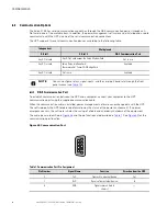
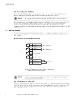
Страница 73: ...e load during any mode of operation the input power must be disconnected from the UPS when the emergency power off function is activated REPO Connections Wire Function Terminal Wire Size Rating Suggested Wire Size REPO L1 12 22 AWG 4 0 32 mm2 18 AWG 0 82 mm2 L2 6 6 3 3 2 2 R Re ella ay y O Ou ut tp pu ut t C Co on nt ta ac ct ts s The UPS incorporates a programmable relay output with potential fre...

Страница 74: ...eration if not prohibited by REPO or an alarm condition Force Bypass If active the UPS is forced to static bypass operation regardless of the bypass status External Battery Breaker Status If active the UPS knows that the batteries are disconnected Building Alarm 1 6 These alarms can be activated separately or at the same time with other building alarms Not in Use Default Shutdown If active the UPS...

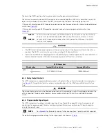
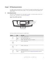
Страница 75: ...useful information about the UPS itself load status events measurements and settings see Figure 51 Figure 51 Eaton 9155 Control Panel Power On Indicator green On Battery Indicator yellow Bypass Indicator yellow Alarm Indicator red Control Buttons for the LCD Menu Options The following table shows the indicator status and description Indicator Status Description Green On The UPS is operating normal...

Страница 76: ...atus UPS off System normal UPS supporting load UPS on battery UPS on bypass Active alarm list Battery status Event Log Displays up to 127 events and alarms Measurements Output L N and L L Current Frequency Power Battery Voltage Current Runtime Input L N and L L Current Frequency Bypass L N and L L Frequency Control Go to Bypass Mode Transfers the UPS to internal Bypass mode When this command is ac...

Страница 77: ... Serial Port Config Port X Slot 1 X Slot 2 Serv Speed 19200 9600 2400 1200 19200 Modem Config Modem Installation Not Installed Set Modem Call Events Event 0 Call modem no Set Modem Init String ATZ0 Set Modem Call Command None Set Modem Communication Password None Start Screen Eaton logo Mimic screen Eaton logo User Password Enabled Disabled If Enabled is selected the password is USER Disabled Audi...

Страница 78: ... 0s Control Commands from X Slot1 Allowed Disabled Allowed Control Commands from X Slot2 Serv Allowed Disabled Allowed X Slot Signal Input Activation Delay 0 through 65 seconds 5s Input signal delayed shutdown delay 1 through 65535 seconds 120s Site Wiring Fault Notice Enabled Disabled Enabled Reset Custom Event Settings 0 through 32 Total 0 32 Auto Output Configuration Enabled Disabled Enabled fo...

Страница 79: ... transformer is installed switch the input circuit breaker to the ON position 3 Switch ON the utility power where the UPS is connected 4 Wait for the front panel LCD to illuminate The indicator flashes 5 Switch all battery circuit breakers to the ON position The indicator stops flashing 6 Press any button on the front panel display to activate the menu options 7 Press the button on the front panel...

Страница 80: ...and are illuminated 7 7 2 2 3 3 I In nt te er rn na all B By yp pa as ss s S St ta ar rt tu up p To start the UPS in internal Bypass mode 1 If you have an optional MBM PDM verify that the maintenance bypass switch is in the UPS position see Figure 52 2 If an optional isolation transformer is installed switch the input circuit breaker to the ON position NOTE When using the optional isolation transf...

Страница 81: ...t td do ow wn n 1 Press any button on the front panel display to activate the menu options 2 Press the button on the front panel display and then press the button to select the TURN UPS ON OFF menu 3 Press the or button to select the TURN UPS OFF option press and hold the button for three seconds until the UPS stops beeping The input contactor opens 4 Repeat Step 3 two times 5 Switch the UPS batte...

Страница 82: ...h Position Description UPS Connects the UPS output to the load SERVICE Connects the load directly to AC input power and disconnects UPS output AC input power is still connected to the UPS input BYPASS Like the SERVICE position BYPASS connects the load directly to AC input power and disconnects UPS output However because BYPASS also disconnects AC input from the UPS this is the appropriate position...

Страница 83: ...tp button Press the Display Functions As the default or after 15 minutes of inactivity the LCD displays the selectable startup screen The default is the Eaton logo and can be changed to the Mimic screen in the User Settings menu The backlit LCD automatically dims after a long period of inactivity Press any button to restore the screen Use the two middle buttons and to scroll through the menu struc...

Страница 84: ...rtin list Battery status For parallel systems System normal B Number x Units on CAN Bus Units on Event Log Displays up to 127 events and alarms Measurements Parallel System parallel UPSs only Voltage by unit Voltage Parallel tota Current Output Frequency Output Pow Output L N and L L Current Frequency Pow Battery Voltage Current Runtime Input L N and L L Current Frequency Bypass L N and L L Freque...

Страница 85: ...PS 2 EBMs 16 UPS 3 EBMs 22 UPS 32 models contain 2 strings EBM 64 models contain 4 strings UPS 64 models contain 4 strings EBM 96 models contain 6 strings 6 Press the button to save the setting 7 Press the ESC button until the Eaton logo appears UPS Operating Instructions ...

Страница 86: ...78 Eaton 9155 UPS 8 15 kVA User s Guide 164201553 Rev H0 UPS Operating Instructions ...

Страница 87: ...lowing requirements should be met Verify that the battery circuit breaker is in the OFF position Avoid temperature and humidity extremes To maximize battery life the recommended storage temperature is 59 F 15 C to 77 F 25 C If you store the UPS for a long period recharge the batteries every 10 months by applying utility power The batteries charge to 80 capacity in approximately 3 hours However it ...

Страница 88: ...ies Released electrolyte is harmful to the skin and eyes It may be toxic CAUTION Do not discard the UPS or the UPS batteries in the trash This product contains sealed lead acid batteries and must be disposed of properly For more information contact your local recycling reuse or hazardous waste center CAUTION Do not discard waste electrical or electronic equipment WEEE in the trash For proper dispo...

Страница 89: ...nd battery charge Save your work and turn off your equipment When utility power is restored the UPS restarts automatically provides power to the load and charges the battery Battery Breaker LED is on 1 beep every second The UPS does not recognize the internal batteries Verify the battery circuit breaker is in the ON position If the condition persists contact your service representative Overload LE...

Страница 90: ...ble at the UPS output receptacles The UPS is in Standby mode Supply power to the connected equipment Press any button on the front panel display to activate the menu options Press the button on the front panel display and then press the button to select the TURN UPS ON OFF menu Press the button to select the TURN UPS ON option press the button Press and hold the button for three seconds until the ...

Страница 91: ...tery and one isolation transformer section 10 kVA 9 kW 9155 10 64 3 high UPS with two battery sections 10 kVA 9 kW 9155 12 32 2 high UPS with one battery section 3 high UPS with one battery and one isolation transformer section 12 kVA 10 8 kW 9155 12 64 3 high UPS with two battery sections 12 kVA 10 8 kW 9155 15 32 2 high UPS with one battery section 3 high UPS with one battery and one isolation t...

Страница 92: ...ating 32 810 ft 10 000m during transportation Relative Humidity 5 95 noncondensing Heat Dissipation 5582 BTU hr maximum online 5294 BTU hr maximum on battery Audible Noise 56 dBA at 1 meter distance typical loads 62 dBA for heavy load high ambient or high altitude on battery Surge Suppression ANSI C62 41 Category B3 Safety Conformance NOM 019 SCFI UL 1778 CSA C22 2 No 107 3 Agency Markings cULus N...

Страница 93: ...ypass is not available in Frequency Conversion mode Output Overload 101 110 for 10 minutes 111 125 for 60 seconds 126 149 for 5 seconds 150 for 300 milliseconds Table 17 Model Specifications 15 kVA Model Output Voltage Line Line 200 220 240 208 220 Output Voltage Line Neutral 100 110 120 120 127 Input Current 71A 71A 71A 71A 67A Output Current 63A 63A 63A 63A 59A Output kVA Line Line Loads 12 5 13...

Страница 94: ...rrent 50A 45A 42A 42A 39A Output kVA Line Line Loads 10 0 10 0 10 0 8 7 8 7 Output kVA Line Neutral Loads 10 0 10 0 10 0 10 0 10 0 Output kW 9 0 9 0 9 0 9 0 9 0 Output Peak Current 110 110 110 110 110 Efficiency Minimum 87 87 87 87 87 Power Dissipation BTU hr 4175 4175 4175 4175 4175 DC Voltage Supply 192 192 192 192 192 8 kVA Model Output Voltage Line Line 200 220 240 208 220 Output Voltage Line ...

Страница 95: ... input current Default 3 4A per string Charging Internal battery approximately 3 hours to 80 usable capacity at nominal line voltage after full load discharge External battery no more than 10x discharge time to 90 usable capacity at nominal line voltage after full load discharge Start on Battery Allows start of UPS without utility input Performance ABM technology increases battery service life opt...

Страница 96: ...s Guide 164201553 Rev H0 Table 19 Battery Runtimes in Minutes at Full Load Continued 8 kVA 7 2 kW 29 91 164 242 NOTE Battery times are approximate and vary depending on the load configuration and battery charge Product Specifications ...

Страница 97: ...te er r 1 11 1 W Wa ar rr ra an nt ty y For warranty information please refer to the Resources link on our website www eaton com 9155 EQUIPMENT REGISTRATION Please visit www eaton com pq register to register your new Eaton UPS Eaton UPS Accessory Model Number Serial Number ...

Страница 98: ...164201553H0 164201553 H0 ...

Отзывы: