Step 4
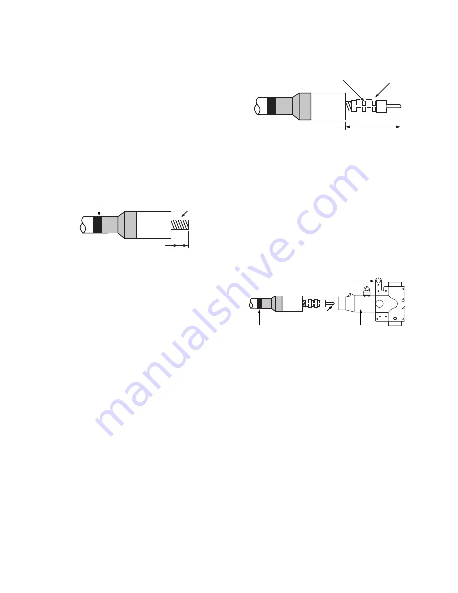
Cable insulation cutback
•
There should be between 4-3/8" and 4-11/16" of exposed
cable beyond the cable adapter. Cut the cable insulation
even with the end of the cable adapter and remove the
protruding cable insulation. Take care not to cut the cable
adapter or nick the conductor.
ote:
N
Alternate insulation removal method
The use of certain insulation removal tools may
require cutting the insulation back before installing
the cable adapter. After removing the semi-
conducting insulation shield, it is acceptable to first
remove 4-1/2" of insulation from the end of the cable.
Then put a 1/8" maximum chamfer in the insulation
and install the cable adapter.
Step 5
Install compression connector
•
Wire brush aluminum conductor and immediately press
compression connector onto the cable until the conductor
bottoms. Copper conductors do not need to be wire
brushed.
•
Rotate the connector so the spade eye faces the
bushing.
•
Crimp the connector using a tool and die combination on
the chart packaged with the connector.
•
Start crimping just below the first line from the spade
end of the connector.
•
Rotate each successive crimp working towards the cable
adapter. Do not overlap crimps.
•
Clean excess inhibitor from the compression connector
and cable adapter surfaces.
•
After crimping, the distance from the cable adapter to the
end of the compression connector must be between
6-1/2" and 7-1/4". Refer to Figure 6.
Step 6
Install PDT625 PUSH-OP body
•
Clean and then lubricate outside of cable adapter.
•
Clean and lubricate inside of PUSH-OP Body.
•
Align PUSH-OP body so that operating eye is oriented
away from apparatus bushing.
•
Slide PUSH-OP body onto cable until compression
connector eye is centered between 600 A interfaces.
(Refer to Figure 7.)
•
Remove tape marker from cable.
Figure 7. Figure 7. Install T-body.
OPERATING EYE
TAPE MARKER
LUBRICATE
CA625
PUSH-OP T-BODY
Figure 5. Remove cable insulation.
TAPE MARKER
4
3
/
8
" (111 mm) - 4
11
/
16
" (119 mm)
CA625
CABLE
CONDUCTOR
Figure 6. Install compression connector.
CA625
PLACE FIRST
CRIMP HERE
COMPRESSION CONNECTOR
6
1
/
2
" – 7
1
/
4
"
(165 mm-184 mm) CHECK
DIMENSION AFTER CRIMPING
3
600 A 15/25 KV CLASS PUSH-OP DEADBREAK CONNECTOR INSTALLATION INSTRUCTIONS
MN650057EN May 2017


