17
ENCODER WIRING/OUTPUT WIRING
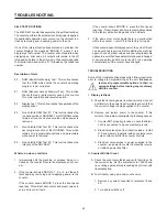
Relay Contact Output Wiring
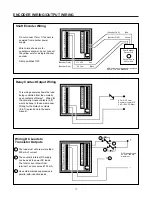
Shaft Encoder Wiring
XXX= Number of pulses per revolution
60,100, 120, 600 Standard
Yellow
+12 VDC Red
DC Com Black
(Encoder Pin D)
Shaft Encoder
Durant Pt #
3815X-XXX or
4837X-XXX
Blue
(Encoder Pin E)
(Encoder Pin A)
(Encoder Pin B)
1
12
2
3
4
5
6
7
8
9
10
11
13
14
15
16
17
18
19
20
21
22
1
12
2
3
4
5
6
7
8
9
10
11
13
14
15
16
17
18
19
20
21
22
Do not connect Term 1 if sensor is
powered from another power
supply.
Wire colors shown are for
quadrature encoder, do not connect
the yellow wire for a single channel
encoder.
All dip switches OFF.
This wiring example shows the load
being controlled from the normally
open contacts of Relay 1. Wiring for
the normally closed contacts (8,9)
would be done in the same manner.
Wiring for the Relay 2 contacts
(5,6,7) is also done in the same
manner.
Load
AC or DC Power
Source for Load (275
VAC, 150 VDC Max.)
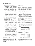
Wiring DC Loads to
Transistor Outputs
1
12
2
3
4
5
6
7
8
9
10
11
13
14
15
16
17
18
19
20
21
22
The load must not draw more than
200 mA of current.
The counter's internal DC supply
can be used to power DC loads.
The total current drawn from
terminal 1 cannot exceed 100 mA.
Use external diode suppression in
parallel with inductive loads.
1
+
Loads
DC Power for Load
30 VDC, 200 mA
maximum.
+
2
3
1
2
3
3


