


CLINK II SCU MANAGER
functional description scu
version 5.0
31
Hard-wired circuits
At the lowest level, motor control takes place with the Remote Control Unit. With this unit start and stop
commands can be given. However, these commands don't pass through the Clink system but interfere directly
in the auxiliary circuit.
Levels and control
•
Motor stop is possible via all control levels
•
Motor start 1 and motor start 2 is not possible via the hard wired control level
•
Motor start via the hard wired control level is only possible with a direct-on-line starter.
Manual control at the switchgear level
The manual control generates commands in the Starter Control Unit as soon as the push-button on the motor
starter tray is pressed.
Warning
Push buttons can not be used for interlocking purposes!
Auxiliary relays
To energize a contactor in the main circuit, the auxiliary relays are (de)energized by a 200 ms pulse. In the
normal course of events, the auxiliary relay K10 is energized and K11 and K12 are not energized (see 9.1 on
page 75 for diagrams). This means that the motor stops running if the Starter Control Unit is no longer
functioning.
5.5.2
Switching conditions
This paragraph describes how a motor can be switched on and off. First an overview is given of the switching
conditions for each starter logic procedure. Then it is shown which external factors can switch a motor on or off.
Switching conditions direct-on-line, star delta, forward reverse, dual speed
•
Start1 and start2 commands are only possible when the isolator is closed.
•
Start1 and start2 commands are only possible if there is no interlocking because of a protection proce-
dure.
•
A stop command is dominant over a start1 or start2 command, in other words a start action is interrupted
by a stop action.
Additional switching conditions forward-reverse
•
If during operation a stop command is given, a start command for the other sense of rotation will be
delayed until the set interlock time has passed.
•
Starting left is not possible during motor starting right.
•
Starting right is not possible during motor starting left.
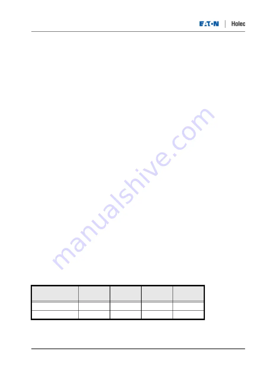
The set points for the running down time (Interlock 1 Time and Interlock 2 Time, see table 23) can be set via
LCU-5. Select:
SCU Manager - Module Control Settings - tab Transfer
..
Table 23: Running down (Interlock) time settings
Name
Range
Default
Unit
Parameter
type
Interlock 1 Time
0-100.00
5
s
Setpoint
Interlock 2 Time
0-100.00
5
s
Setpoint


