background image

SPINDLE AND SUPPORT ARM “TEE” BEAM ASSEMBLY [H] & [D] TO 
MAIN SUPPORT FRAME & SPINDLE SUPPORT ASSEMBLY [A] & [E].

1. 

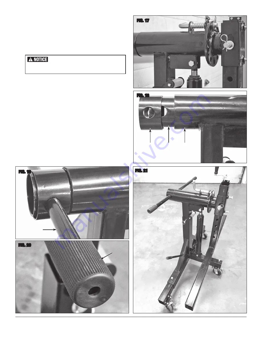
Remove the Retaining Clip and Washer from the Spindle Latch Pin and 
set aside for reinstallation.

2. 

Apply a liberal amount of high-quality synthetic, high-load wheel 
bearing grease or an anti-seize compound to the bearing surfaces of 
the Spindle Support and outside of the Spindle before insertion.


3. 

Lift the Spindle and “Tee” Beam Assembly 

[H]

 and 

[D]

 and insert the 

Spindle into the Sleeve. Push it in fully engaging the Latch Pin with the 
hole nearest the 12:00 position of the 10 in the Rotation Lock Plate 

(FIG 17)

.

4. 

Reinstall the previously removed Retaining Clip and Washer onto the 
Spindle Latch Pin 

(FIG 17)

.

5. 

Slide the Spindle Retaining Collar 

[J]

 over the protruding inboard end 

of the Spindle 

[H]

 and align the through holes 

(FIG 18)

6. 

Insert the Spindle Rotating Bar 

[K]

 through the Spindle Retaining  

Collar 

[J]

 and the Spindle 

[H] (FIG 19)

.

7. 

Push the rubber Spindle Rotating Bar Grips 

[L]

 fully onto the ends of 

the Spindle Rotating Bar 

[K] (FIG 20)

.

8. 

The assembly should appear as in 

FIG 21

. Repeat assembly procedure 

for opposite end.

To order parts and supplies: 800.343.9353  >>  eastwood.com 

9


  The assistance of a capable assistant is required for 

the following step.

FIG. 17

FIG. 18

FIG. 19

FIG. 20

FIG. 21

E

H

J

K

L

Содержание 32194

Страница 1: ...3000 LB ROTISSERIE INSTRUCTIONS Item 32194 ...

Страница 2: ...mmodate large vehicle bodies and projects CONTENTS COMPONENTS 2 Main Support Frame Assemblies A 4 Caster Arms B 6 Locking Swivel Casters C 2 Support Arm Tee Beams D 2 Spindle Support Assemblies E 2 Hydraulic Cylinders F 2 Hydraulic Cylinder Control Handles G 2 Spindle Assemblies H HARDWARE 24 M10 x 25mm Bolts washers lock washers and nuts 2 Cotter Pins A B C D E F G H J K L M A B B B E H D N R P H...

Страница 3: ... it on the Rotisserie DO NOT exceed the rated 3000lb 1360kg 1500 lbs 680kg per end weight capacity DO NOT use to support humans or animals DO NOT climb on the Rotisserie DO NOT use the Rotisserie to support items other than auto body shells chassis frames or pickup cabs DO NOT attempt to transport this Rotisserie with a load attached by any hauling method DO NOT remove or cover any of the factory ...

Страница 4: ...this Rotisserie without assistance The use of ANSI approved safety shoes head protection gear and eye protection is necessary Perform assembly in a large uncluttered area close to area of intended use Allow sufficient area for operator and helper to remain clear when choosing operating area Use only on a firm smooth level and clean work surface DO NOT use on a sloped or rough textured surface eart...

Страница 5: ...embly A with the Vertical Post with Roller standing upward FIG 1 2 Attach a Locking Swivel Caster C to flange of Main Support Assembly A using four M10 x 25mm Bolts Washers Lockwash ers and Nuts Tighten securely using two 17mm wrenches not included FIG 2 3 Attach Locking Swivel Casters C to flanges of Caster Arms B using four M10 x 25mm Bolts Washers Lockwashers and Nuts FIG 3 Tighten securely usi...

Страница 6: ... Bearing from the end of the Jackscrew and set aside for re installation FIG 6 5 Insert the machined M12 threaded end of the Jackscrew through the holes in the Crossbeam of the Support Arm Tee D with the M12 threads visible on the opposite side 6 Reinstall the 3 pieces of the Bearing using care to install the components in the proper direction and sequence FIG 7 Secure with the M12 Locknut and tig...

Страница 7: ...Arm Tee Beam with the previously removed M6 x 20 Screws Washers Locknuts and secure with two 10mm wrenches not included FIG 10 4 Replace the Crank Handle over the flats on the end of the Jackscrew with the Handle upward and secure with the M12 Nut and Washer Tighten securely with a 19mm wrench not included FIG 11 5 Turn the Crank as needed to raise or lower the Support Arm Tee Beam D as needed to ...

Страница 8: ...der F to fall forward SPINDLE SUPPORT ARM E TO MAIN SUPPORT FRAME ASSEMBLY A AND HYDRAULIC CYLINDER F 1 Remove the M16 x 80mm Locknut and Washer from the cylinder mounting plates at the underside of the Spindle Support E FIG 15 and set aside for reinstallation 2 With the Latch Pin facing forward slide the square tube post of the Spindle Assembly H D down into the larger square tube upright of the ...

Страница 9: ...t the 12 00 position of the 10 in the Rotation Lock Plate FIG 17 4 Reinstall the previously removed Retaining Clip and Washer onto the Spindle Latch Pin FIG 17 5 Slide the Spindle Retaining Collar J over the protruding inboard end of the Spindle H and align the through holes FIG 18 6 Insert the Spindle Rotating Bar K through the Spindle Retaining Collar J and the Spindle H FIG 19 7 Push the rubber...

Страница 10: ...nec tor Beams N into the ends of the Large Connector Beams M Do Not allow the Beam to extend beyond the minimum insertion lines marked at 4 10cm from the Beam end FIG 24 Lightly tighten the Lockbolt with a 21mm wrench not included to keep Beam from sliding 4 Slip the non lockbolt end of each of the single Small Connector Beam P into the ends of the Intermediate Connector Beams N Do Not allow the B...

Страница 11: ... determined tighten the Lockbolts with a 21mm wrench not included FIGS 26 27 The Eastwood Rotisserie is now ready for use FIG 28 To order parts and supplies 800 343 9353 eastwood com 11 It is extremely important that the Attachment Arms be set at an equal distance from the centerline of the Support Tee Beam when mounting a vehicle body to avoid a dangerous out of balance condition FIG 25 FIG 26 FI...

Страница 12: ...FACE OF SUPPORT ARM TEE BEAMS D FIG 29 1 Loosen the Lockbolts on the Support Arm Tee Beams D then carefully slide out the Large Connector Beams M exercising extreme care not to exceed the minimum exposure depth Lightly tighten the Lockbolts 2 Loosen the Lockbolts on the Large Connector Beams M then then carefully slide out the Intermediate Connector Beams N ex ercising extreme care not to exceed t...

Страница 13: ... 1 Remove the Lock Pin Washer and Clip from the Main Support Frame A and Spindle Support E 2 Using the Hydraulic Cylinders F move the Spindle up or down as required to place it in line with the balance centerline of the vehicle body 3 Align the holes in Main Support Frame A with the nearest of 7 holes in Spindle Support E then replace the Lock Pin Washer and Clip Support Arm Tee Beam D Fine Tuning...

Страница 14: ...ate the Jackscrew Handcranks at the same time to fine tune and raise the vehicle body centerline nearer to the spindle centerline 8 Once the balance point is reached reinstall the Lockpins Clips and Washers into the Spindles H and Support Arm Tee Beams D 9 As the vehicle body is rotated into the desired position remove Clips Lockpins and Washers from the Spindle Latch Pins release them form the re...

Страница 15: ...e Post Roller Bushings Caster Zerk Fittings The Rotisserie is finished in rugged powdercoating which will provide many years of effort free beauty however it is advisable to keep the finish clean and free from excessive dust and dirt Keep the Rotisserie in a clean and dry environment DO NOT store it in or expose it to a damp or wet environment Occasionally inspect all components for potential dama...

Страница 16: ...estions about the use of this product please contact The Eastwood Technical Assistance Service Department 800 343 9353 email techelp eastwood com PDF version of this manual is available at eastwood com The Eastwood Company 263 Shoemaker Road Pottstown PA 19464 USA 800 343 9353 eastwood com ...

Отзывы: