6
Eastwood Technical Assistance: 800.343.9353 >> [email protected]
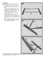
TOP AND FENCES TO FRAME
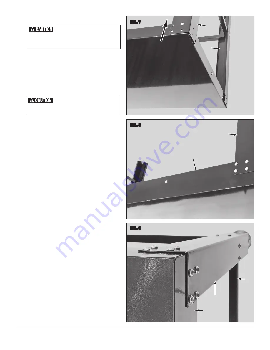
• With a helper, flip the Frame Assembly so that the open
“Front” (without Brace) side is facing upward and the Back
(with Long Brace) is against the floor.
• Again, with the aid of a helper, slide the Top
[G]
carefully into
position with the edge containing the three threaded Inserts
also facing upward by aligning all the slotted holes in the cor-
ners with those in the top of the Legs
[A]
,
[B]
&
[C]
(FIG 7)
.
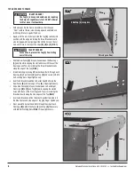
• Slip the Rear Fence
[H]
into position between the Rear Legs
[A]
and Top while aligning the slotted holes with those of the
Rear Legs and Top also including the three threaded Inserts
along the edge of the Top
(FIG 8)
.
• Immediately begin placing M8 Socket Head Bolts through each
Rear Leg
[A]
, Rear Fence
[H]
and Top
[G]
and secure with M8
Self-Locking Nuts. Finger tighten only.
• Insert and thread three M8 x 15 Socket Head Bolts into the
Rear Fence
[H]
and rear edge of Top
[G]
. Finger tighten only.
• Slip a Side Fence
[J]
into position between Left and Right
Front Legs
[B]
&
[C]
and Top
[G]
while aligning the slotted
holes with those of the Front Legs and Top also including the
threaded Inserts along the side edges of the Top
(FIG 9)
.
• Insert and thread one M8 x 15 Socket Head Bolt per side into
the Side Fences and side edges of Top
[G]
. Finger tighten only.
• Next, place M8 Socket Head Bolts through the side of each
Front Leg
[B]
&
[C]
, Side Fence
[J]
and Top
[G]
then secure
with M8 Self-Locking Nuts
(FIG 9)
. Finger tighten only.
FIG. 7
FIG. 8
FIG. 9
INJURY HAZARD!
The Top [G] is heavy and cumbersome requiring
the help of a capable assistant. DO NOT attempt
to lift or move it without help.
INJURY HAZARD!
Use caution to prevent the Top [G] from falling
over at this step.
✓
A
✓
✓
B
Slide Top [G] into place
Le
g a
gai
ns
t fl
oo
r
This edge on floor
A
✓
H
✓
G
G
✓
✓
✓
H
A
E
F
J
Содержание 31654
Страница 1: ...MODULAR WORK BENCH INSTRUCTIONS Item 31654...


